Computer aided treatment planning and visualization with image registration and fusion

a technology of image registration and fusion, applied in the field of surgical planning, can solve the problems of stenosis analysis and plaque removal planning, limited spatial relationship representation of 2d slice images, and underestimate the plaque burden

Inactive Publication Date: 2008-04-08
THE RES FOUND OF STATE UNIV OF NEW YORK
View PDF63 Cites 217 Cited by
  • Summary
  • Abstract
  • Description
  • Claims
  • Application Information

AI Technical Summary

Benefits of technology

[0011]It is an object of the present invention to provide a method of flexible image registration suitable for use in three dimensional (3D) visualization systems.

Problems solved by technology

However, the 2D slice images are limited in their ability to represent the spatial relationships between adjacent and interrelated structures.
For example, a retro-displaced bifurcation point of carotid arteries might make stenosis analysis and plaque removal planning difficult.
Carotid artery stenosis is the most common cause of stroke, which is a major health care problem, that affects more than 700,000 Americans each year.
In fact, this condition is the leading cause of disability and the third leading cause of deaths in the United States, after cardiovascular disease and cancer.
However, luminal narrowing is an indirect marker of plaque size and may underestimate the plaque burden as plaque may grow inside the vessel wall from the lumen towards the outer surrounding tissues.
However, neither imaging technology alone is sufficient to provide a complete analysis of the size, composition and position of the plaque buildup.
In MR image data, the inter-slice and even intra slice image data often contains spatial inhomogeneity which adversely affects automated analysis of these images.

Method used


Image

  • Computer aided treatment planning and visualization with image registration and fusion
  • Computer aided treatment planning and visualization with image registration and fusion
  • Computer aided treatment planning and visualization with image registration and fusion

Examples


Embodiment Construction

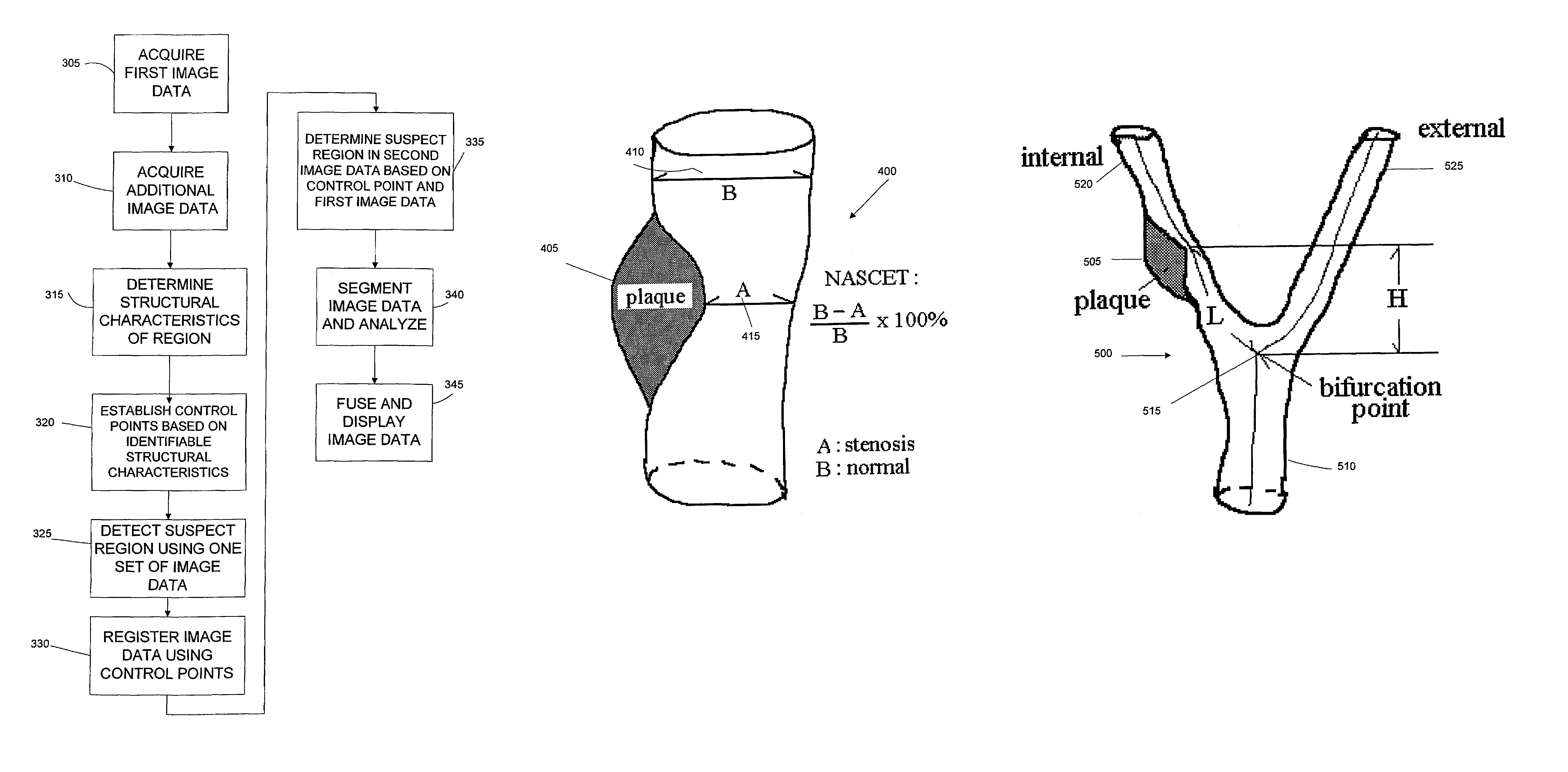
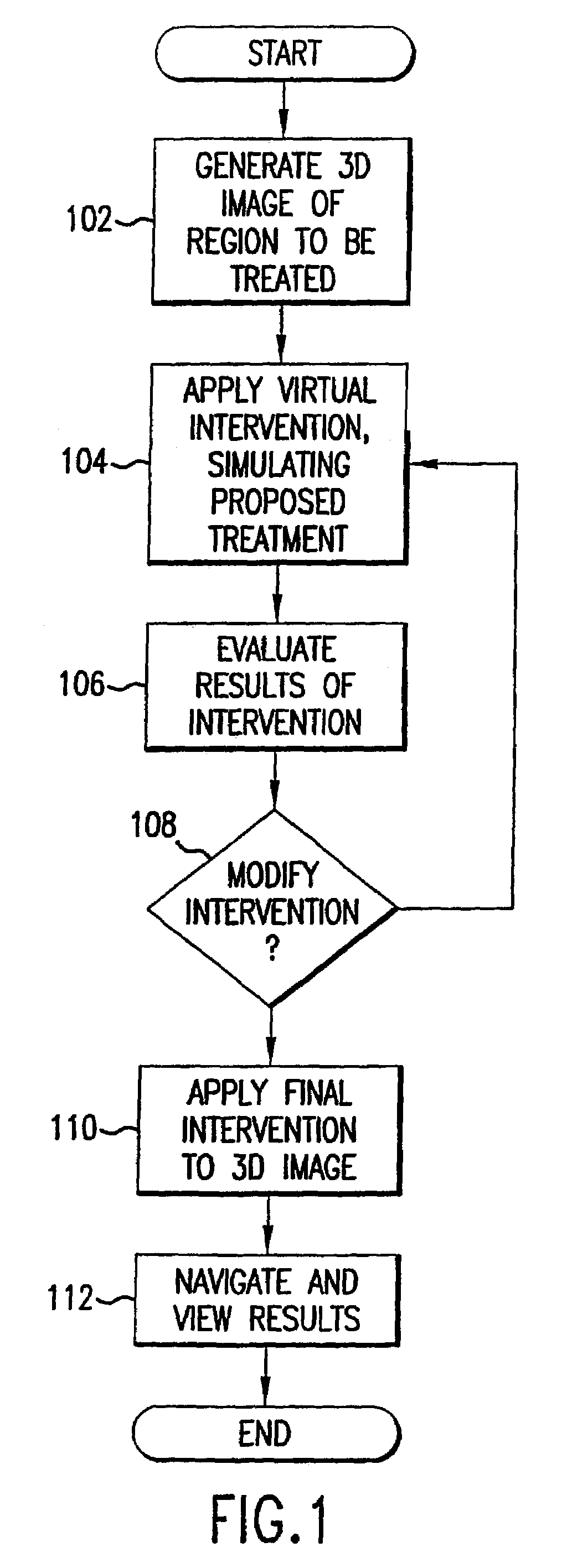
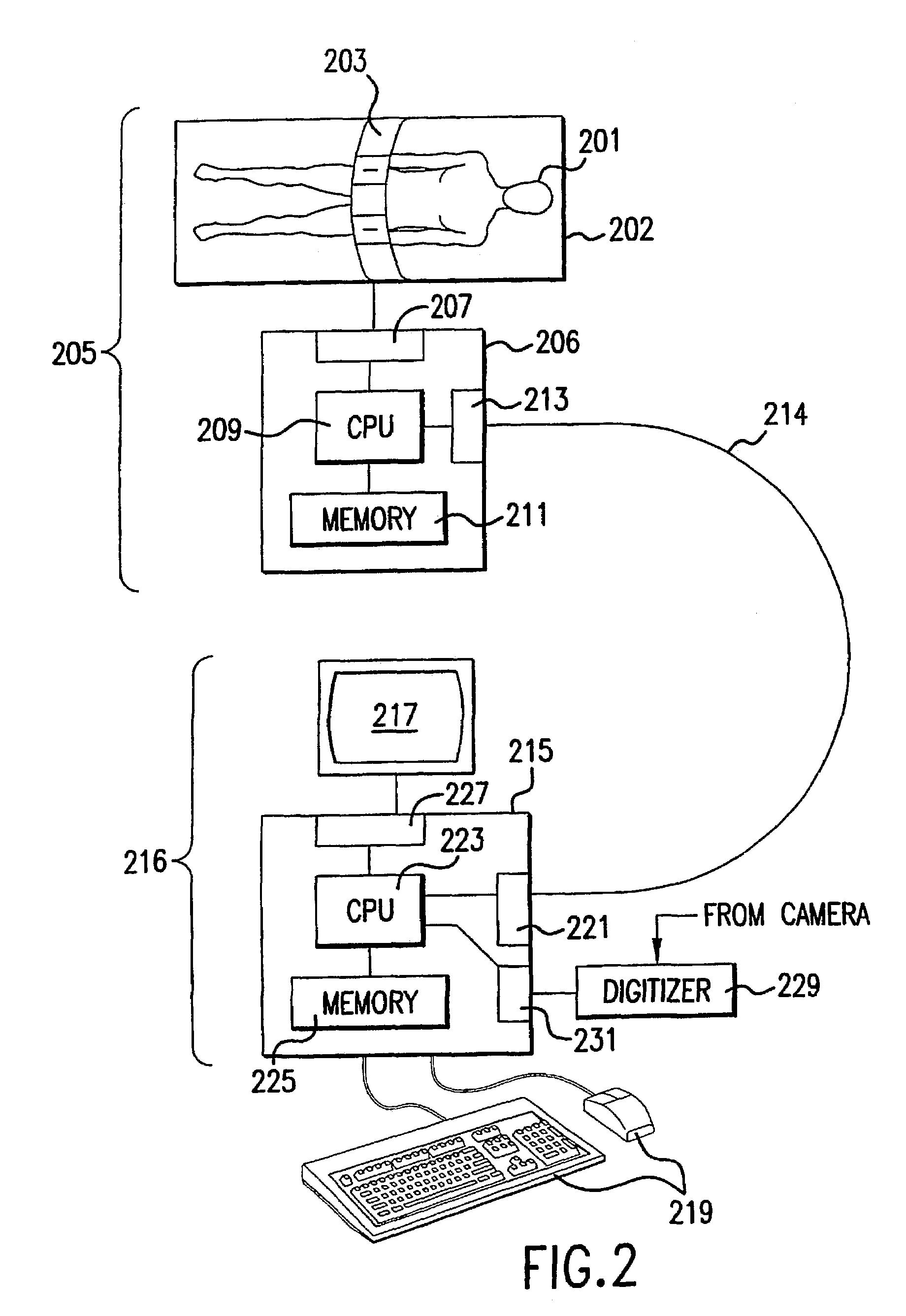
[0031]FIG. 1 is a flow chart which illustrates an overview of the present method of computer aided treatment planning and interactive visualization which is generally performed on a computer based system, such as that illustrated in FIG. 2. The invention will be described in terms of medical applications performed on human patients and in the context of medical treatment, such as examination (e.g., measuring carotid stenosis and quantifying plaque components), surgery (e.g., removal of carotid plaque), prosthesis implantation, biopsy, medication, therapeutic radiation, therapeutic ultrasound and the like. It will be appreciated, however, that the invention is not limited to human patients, nor to the exemplary list of treatments referenced. The term treatment is used to mean an intervention in a region, such as but not limited to tissue, that is intended to effect an alteration of the region.

[0032]Referring to FIG. 1, the method includes the initial step of generating a three dimens...


PUM


Abstract

A computer based system and method of visualizing a region using multiple image data sets is provided. The method includes acquiring first volumetric image data of a region and acquiring at least second volumetric image data of the region. The first image data is generally selected such that the structural features of the region are readily visualized. At least one control point is determined in the region using an identifiable structural characteristic discernable in the first volumetric image data. The at least one control point is also located in the at least second image data of the region such that the first image data and the at least second image data can be registered to one another using the at least one control point. Once the image data sets are registered, the registered first image data and at least second image data can be fused into a common display data set. The multiple image data sets have different and complimentary information to differentiate the structures and the functions in the region such that image segmentation algorithms and user interactive editing tools can be applied to obtain 3d spatial relations of the components in the region. Methods to correct spatial inhomogeneity in MR image data is also provided.

Description

GOVERNMENT INTERESTS[0001]The invention disclosed herein was made with Government support under NIH Grant CA 79180. Accordingly, the U.S. Government may have certain rights in this invention.FIELD OF THE INVENTION[0002]The present invention relates generally to surgical planning and more particularly relates to systems and methods of registering, segmenting and analyzing image data for three dimensional interactive computer visualization and surgical planning and follow-up evaluation.BACKGROUND OF THE INVENTION[0003]In many areas of medical treatment, it would be beneficial for a medical practitioner to be able to visualize a region for which treatment is contemplated and to accurately simulate the contemplated treatment. By visualizing the effect of the simulated treatment and altering the proposed treatment to optimize the results in a virtual setting, results can be improved and risks associated with the actual treatment can be reduced. This is particularly true in the case of in...

Claims


Application Information

Patent Timeline
Patent Type & Authority Patents(United States)
IPC IPC(8): A61B5/05A61B5/055A61B19/00
CPCA61B5/055A61B19/52A61B5/726A61B2019/5289A61B90/36A61B2090/364
Inventor LIANG, ZHENGRONGCHEN, DONGQINGLI, BINROQUE, CLEMENTE T.SMOUHA, ERIC E.KAUFMAN, ARIE E.WAX, MARK R.KREEGER, KEVIN
Owner THE RES FOUND OF STATE UNIV OF NEW YORK
Why Eureka
Try Eureka