Method and device for placing dental implants

a technology for dental implants and dental prosthesis, applied in dental prosthesis, dentistry, medical science, etc., can solve the problems of compromising the safety of intervention, not fully utilizing the possibilities and advantages of computer simulation, and major inconvenien

Inactive Publication Date: 2011-11-10
DENTSPLY IMPLANTS NV
View PDF5 Cites 213 Cited by
  • Summary
  • Abstract
  • Description
  • Claims
  • Application Information

AI Technical Summary

Benefits of technology

[0036]The method according to the invention also has the advantage that a set of washers with inside diameters corresponding to the diameter of the fixture mounts can be pre-produced. When necessary, during a second intermediate stage, the placement of one or more of these washers on the fixture mounts allows to control the depth of penetration of the implants.

Problems solved by technology

This method makes it possible to obtain a precise surgical template, but does not completely make use of the possibilities and the advantages of a computer simulation, as this template is obtained by recreating the implant simulation by moulding staring from a real bone model and not from a viral model.
Moreover, the drilling tubes are maintained in place in the cylinders by a flange and a clamping screw, which represents a major inconvenience.
Besides the handling difficulties linked both to the placement and to the control of such a high number of elements in a patient's mouth, and to the instability of their fixation, the system of drilling tubes of varying diameter held by screws also compromises the safety of the intervention as it remains possible that one of the pieces is ingested.
Nevertheless, the need to use a plurality of templates somewhat reduces the advantages of the simplification obtained by making use of the method of the company Materialise.
It is thus clear from the documents cited above that different methods and devices for the placement of dental implants are known in the state of the art; nevertheless, these methods and devices do not entirely meet the needs of the practitioner, who is still limited by too many constraints in their use.

Method used


Image

  • Method and device for placing dental implants
  • Method and device for placing dental implants
  • Method and device for placing dental implants

Examples


Embodiment Construction

[0016]The present invention relates to a method and a device for the placement of dental implants which aims to eliminate the constraints related to the use of the methods and systems of the prior art.

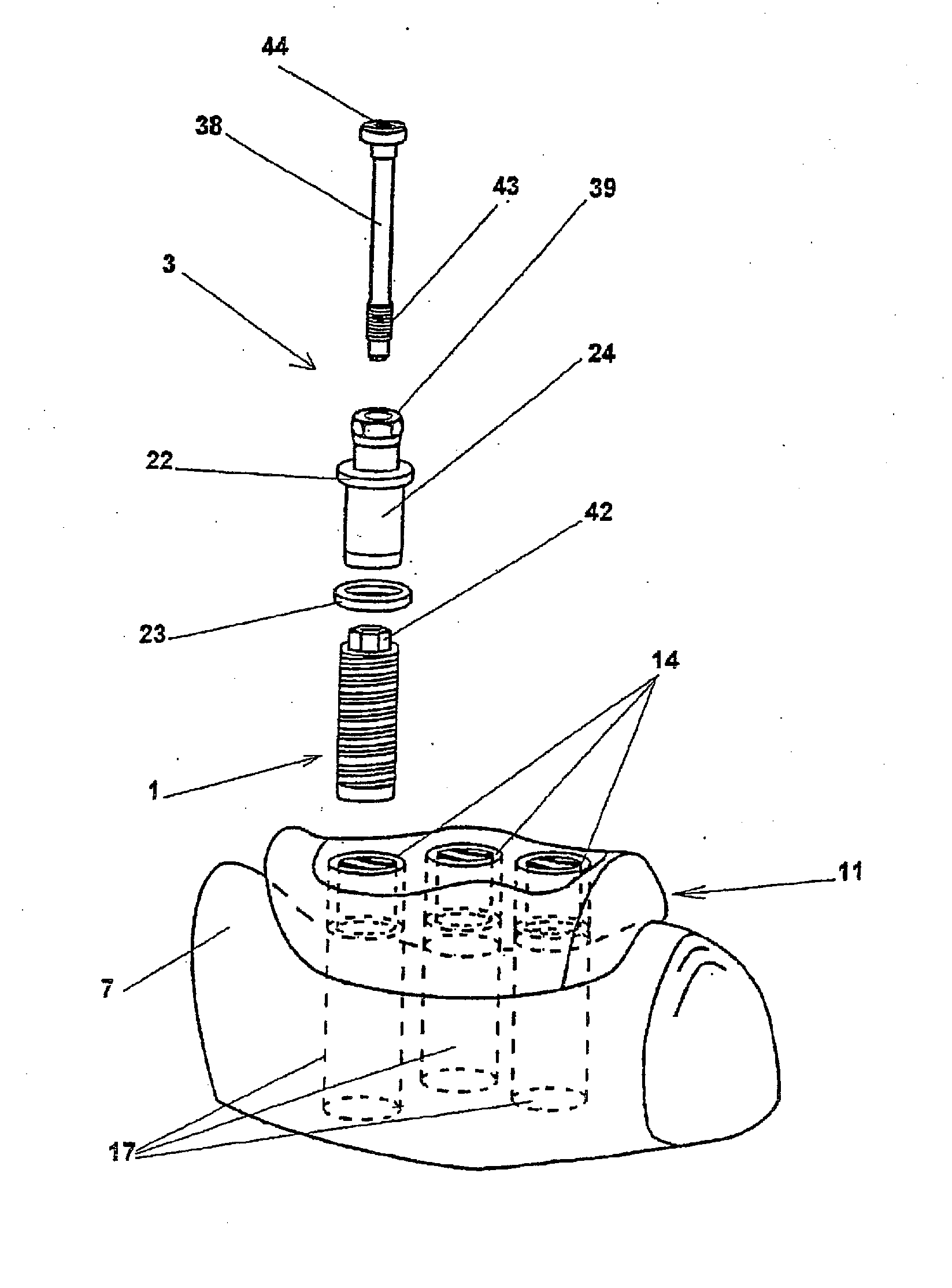
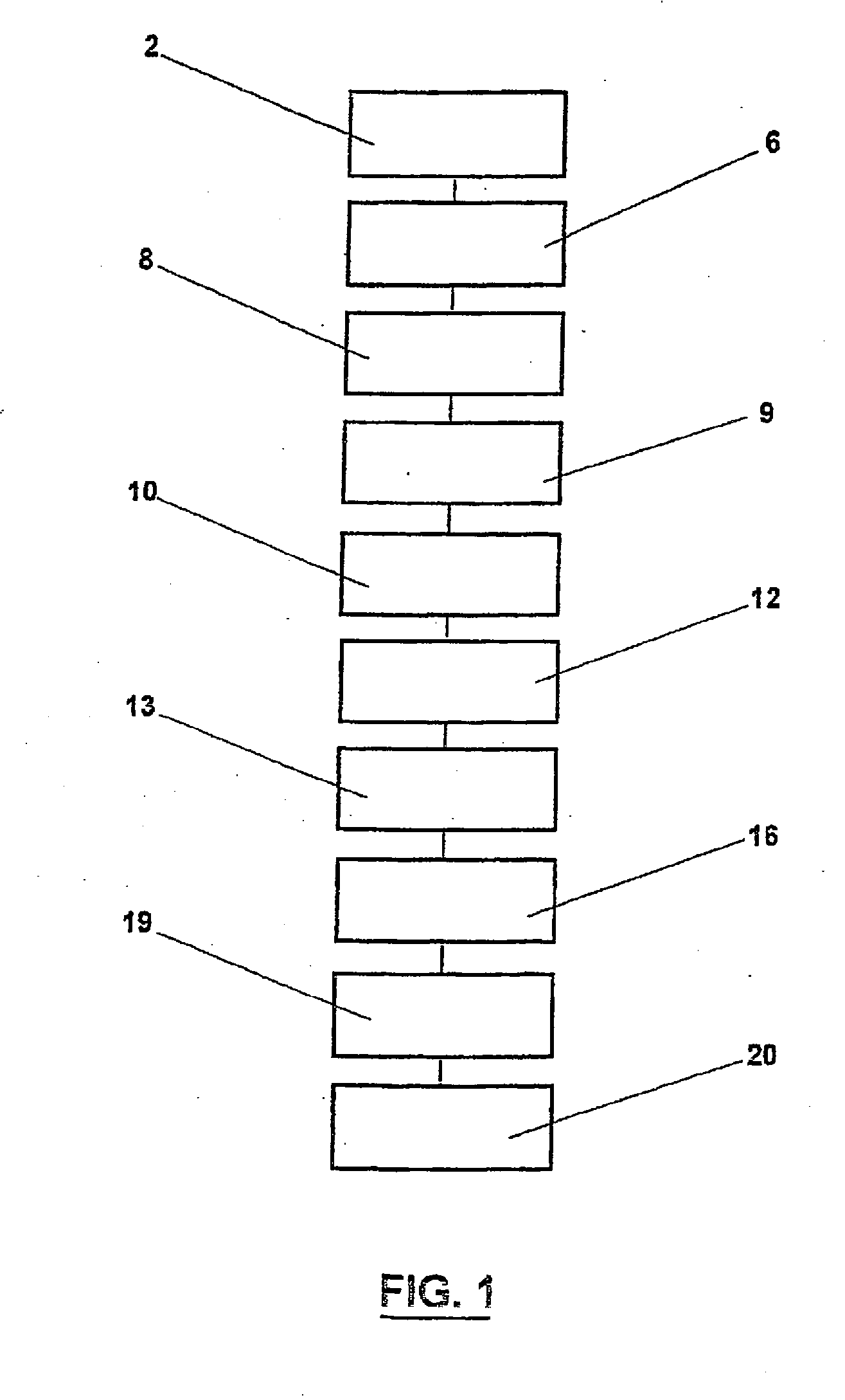
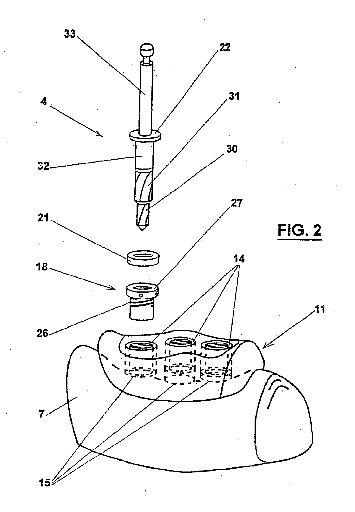
[0017]More specifically the object of the invention is a method of the type comprising following steps:[0018]a) placement in the mouth of the patient of a scannographic guide,[0019]b) acquisition by the computer of the scanner data of the guide, as well as of the mandible or the maxilla of the patient,[0020]c) simulation on the computer of the mandible or the maxilla starting from the scanner data,[0021]d) generation by the computer, under control of the practitioner, of implant planning parameters based on this simulation,[0022]e) control by computer based on the planning parameters of a device for the production of a template featuring bore tubes with predetermined inclinations and positions,[0023]f) securing in these bore tubes guiding cylinders of one single standard dimension pred...


PUM


Abstract

The invention relates to a method and device for placing implants using a surgical template which is made from tomographic cuts in the patient's jawbone. Step drills and calibrating drills, having a single standard diameter for each type of implant, are guided through drill bushings which are inserted into bores in the template in order to produce any drilling sequence corresponding to an implant plan. The penetration depth of the drills is controlled by the height of the bores or by the drill rings. The method limits the required number of drills and implant supports to the longest models only. The inventive method and device are particularly suitable for computer-assisted implantology systems.

Description

CROSS-REFERENCE TO RELATED APPLICATIONS[0001]This application is a continuation of U.S. patent application Ser. No. 12 / 421,919, filed Apr. 10, 2009, which is a divisional of U.S. patent application Ser. No. 10 / 505,846, filed Aug. 26, 2004, which is the U.S. National Stage Application of International Patent Application No. PCT / FR03 / 00667, filed Feb. 28, 2003, which claims priority to FR 02 / 02587, filed Feb. 28, 2002.TECHNICAL FIELD OF THE INVENTION[0002]The present invention relates to a method and a device for placing dental implants.BACKGROUND OF THE INVENTION[0003]Esthetical considerations or therapeutic indications often lead to the replacement of missing teeth of a highly deteriorated denture of a patient by an implant. The most common prostheses are still the tooth or tissue borne prosthesis, while the placement of prostheses anchored in the mandible or the maxilla of the patient by way of one or more implants screwed into holes drilled in the boney tissue is being developed.[...

Claims


Application Information

Patent Timeline
Patent Type & Authority Applications(United States)
IPC IPC(8): A61C13/38A61C8/00A61C1/08
CPCA61C8/0089A61C1/084A61C1/08A61C8/00
Inventor TARDIEU, PHILIPPEVRIELINCK, LUC
Owner DENTSPLY IMPLANTS NV
Why Eureka
Try Eureka