Rotating field sensor

a sensor and rotating field technology, applied in the direction of magnetic measurement, instruments, nanomagnetism, etc., can solve the problems of reducing the installation location of magnetic detection elements, and affecting the accuracy of detection.

Active Publication Date: 2014-02-25
TDK CORPARATION
View PDF7 Cites 14 Cited by
  • Summary
  • Abstract
  • Description
  • Claims
  • Application Information

AI Technical Summary

Benefits of technology

[0015]It is an object of the present invention to provide a rotating field sensor that makes it possible to reduce the error in a detected angle resulting from a noise field and reduce the installation locations of magnetic detection elements.
[0022]A noise field other than the rotating magnetic field may be applied to the rotating field sensor of the present invention from outside. In this case, the first applied field may be a composite magnetic field resulting from a combination of the first partial magnetic field and the noise field, and the second applied field may be a composite magnetic field resulting from a combination of the second partial magnetic field and the noise field. When a noise field other than the rotating magnetic field is applied to the rotating field sensor of the present invention from outside, the error in the first detected angle value resulting from the noise field and the error in the second detected angle value resulting from the noise field have values of opposite sign. Consequently, according to the present invention, it is possible to reduce the error in the detected angle resulting from the noise field.
[0033]According to the present invention, as described above, when a noise field is applied to the rotating field sensor from outside, the error occurring in the first detected angle value due to the noise field and the error occurring in the second detected angle value due to the noise field have values of opposite sign. Consequently, according to the present invention, it is possible to reduce the error in the detected angle resulting from the noise field. The foregoing effect of the present invention is provided by the arrangement of the first and second detection units in the first and second positions. The present invention thus makes it possible to reduce the error in the detected angle resulting from the noise field and also reduce the installation locations of the magnetic detection elements.

Problems solved by technology

If the rotating magnetic field to detect and the noise field differ in direction, the angle detected by the rotating field sensor includes some error.
As a result, the angle detected by the rotating field sensor includes an error of 0.14°.
This shows that if, for example, an angle accuracy (resolution) of 0.1° is required of the angle to be detected by the rotating field sensor, even the earth's magnetism can be an extremely large noise source.
Such measures, however, have the drawbacks of making the design of the rotating field sensor including the magnetic shield large in scale, increasing the cost of the rotating field sensor, and placing various constraints on the assembly steps and on the installation of the rotating field sensor.
In the rotation detecting apparatus described in JP-A-2009-186410, however, a noise field produces errors of opposite sign in the respective output signals of the pair of magnetic detection elements.
The rotation angle detecting apparatus described in JP-A-2005-315696 thus has a drawback that its application is limited to cases where the four magnetic detection elements can be arranged at intervals of 90°.

Method used


Image

  • Rotating field sensor
  • Rotating field sensor
  • Rotating field sensor

Examples


first embodiment

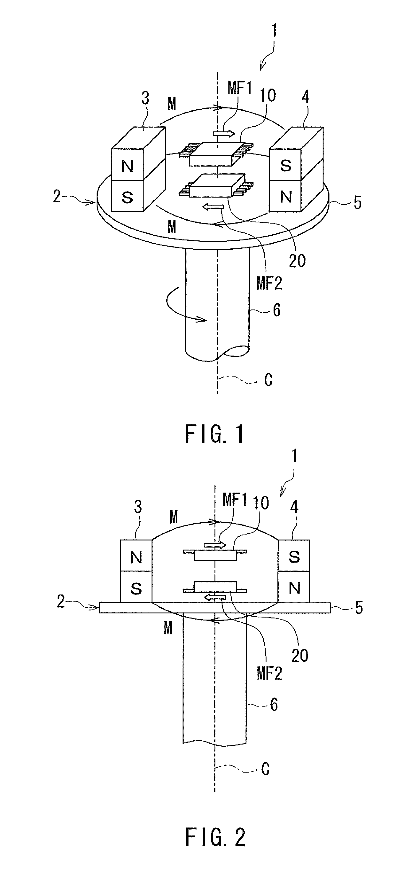
[0062]Preferred embodiments of the present invention will now be described in detail with reference to the drawings. First, reference is made to FIG. 1, FIG. 2, FIG. 4A and FIG. 4B to describe the general configuration of a rotating field sensor according to a first embodiment of the invention. FIG. 1 is a perspective view showing the general configuration of the rotating field sensor according to the present embodiment. FIG. 2 is a side view showing the general configuration of the rotating field sensor according to the present embodiment. FIG. 4A and FIG. 4B are explanatory diagrams illustrating the definitions of directions and angles in the present embodiment.

[0063]The rotating field sensor 1 according to the present embodiment detects the angle that the direction of a rotating magnetic field in a reference position forms with respect to a reference direction. The rotating magnetic field includes a first partial magnetic field MF1 in a first position and a second partial magneti...

modification examples

[0108]First and second modification examples of the present embodiment will now be described. First, a description will be given of a rotating field sensor 1 of the first modification example of the embodiment with reference to FIG. 7. FIG. 7 is a side view showing the general configuration of the rotating field sensor 1 of the first modification example. In the first modification example, the pair of magnets 3 and 4 are tilted with respect to the center of rotation C so that the distance between the magnets 3 and 4 increases with increasing distance from the top surface of the disc part 5. The N and S poles of the magnet 3 are arranged obliquely to the center of rotation C, in the order of the S pole and the N pole in the direction away from the top surface of the disc part 5. The N and S poles of the magnet 4 are arranged obliquely to the center of rotation C, in the order of the N pole and the S pole in the direction away from the top surface of the disc part 5.

[0109]In FIG. 7, t...

second embodiment

[0112]A rotating field sensor according to a second embodiment of the invention will now be described with reference to FIG. 9 and FIG. 10. FIG. 9 is a perspective view showing the general configuration of the rotating field sensor according to the present embodiment. FIG. 10 is a side view showing the general configuration of the rotating field sensor according to the present embodiment. As shown in FIG. 9 and FIG. 10, the rotating field sensor 61 according to the present embodiment has a field generation unit 62 instead of the field generation unit 2 of the first embodiment.

[0113]The field generation unit 62 has a ring-shaped magnet 63. The magnet 63 is attached to a rotating shaft 66 which is the object whose rotational position is to be detected. In FIG. 9 and FIG. 10, the dot-and-dash line designated by symbol C shows the center of rotation including the center axis of the rotating shaft 66. The magnet 63 is fixed to the rotating shaft 66 by not-shown fixing means so as to be s...


PUM


Abstract

A field generation unit generates a rotating magnetic field including a first partial magnetic field in a first position and a second partial magnetic field in a second position. The first and second partial magnetic fields differ in direction by 180° and rotate in the same direction of rotation. A first detection unit detects, in the first position, a first angle that the direction of a first applied field forms with respect to a first direction. The first applied field includes the first partial magnetic field as its main component. A second detection unit detects, in the second position, a second angle that the direction of a second applied field forms with respect to a second direction. The second applied field includes the second partial magnetic field as its main component. A detected value of the angle that the direction of the rotating magnetic field in a reference position forms with respect to a reference direction is calculated based on detected values of the first and second angles.

Description

BACKGROUND OF THE INVENTION[0001]1. Field of the Invention[0002]The present invention relates to a rotating field sensor for detecting an angle that the direction of a rotating magnetic field forms with respect to a reference direction.[0003]2. Description of the Related Art[0004]In recent years, rotating field sensors have been widely used to detect the rotational position of an object in various applications such as detecting the rotational position of an automotive steering wheel. Rotating field sensors are used not only to detect the rotational position of an object but also to detect a linear displacement of an object. Systems using rotating field sensors are typically provided with means (for example, a magnet) for generating a rotating magnetic field whose direction rotates in conjunction with the rotation or linear movement of the object. The rotating field sensors use magnetic detection elements to detect the angle that the direction of the rotating magnetic field forms wit...

Claims


Application Information

Patent Timeline
Patent Type & Authority Patents(United States)
IPC IPC(8): G01B7/14G01R33/02G01B7/30
CPCB82Y25/00G01R33/093
Inventor SARUKI, SHUNJIHIRABAYASHI, HIRAKU
Owner TDK CORPARATION
Why Eureka
Try Eureka