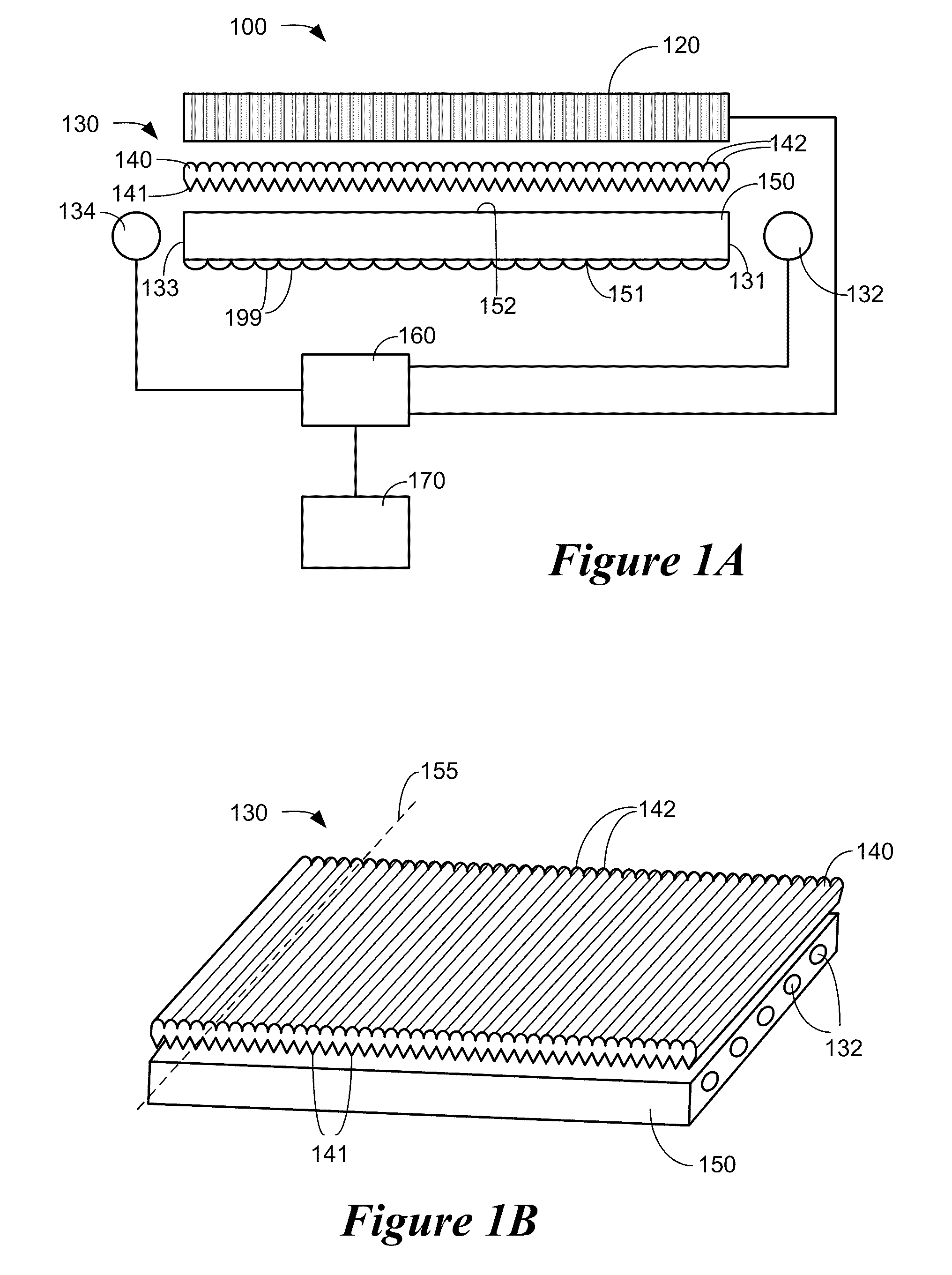
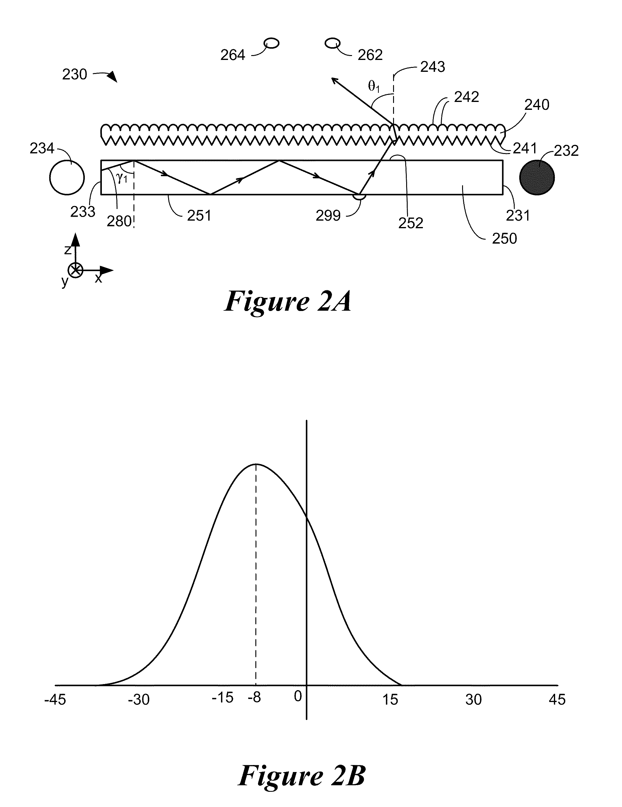
Optical films enabling autostereoscopy
a technology of optical films and autostereoscopy, applied in the field of optical films enabling autostereoscopy, can solve the problems of degrading the viewing experience and degrading the image observed by the viewer
- Summary
- Abstract
- Description
- Claims
- Application Information
AI Technical Summary
Benefits of technology
Problems solved by technology
Method used
Image
Examples
example 1
[0102]A display with an optical film having cylindrical lenses and varying prism pitch was simulated using ray tracing. The ray tracing software used was TracePro, a non-sequential ray tracing package (Lambda Research Corporation, Littleton, Mass.).
[0103]Display characteristics: WVGA (800×480 pixels); 196.8 mm (width)×118.08 mm (height); Viewing distance 750 mm, implying that the nominal eye separation of the viewer is + / −2.4 degrees.
[0104]As illustrated in FIG. 7A, for viewer positioned at 710, the left edge 722 of the display 720 is at an angle of 7.5 degrees from normal, assuming a display width of 196.4 mm and a viewing position of 750 mm above the display 720.
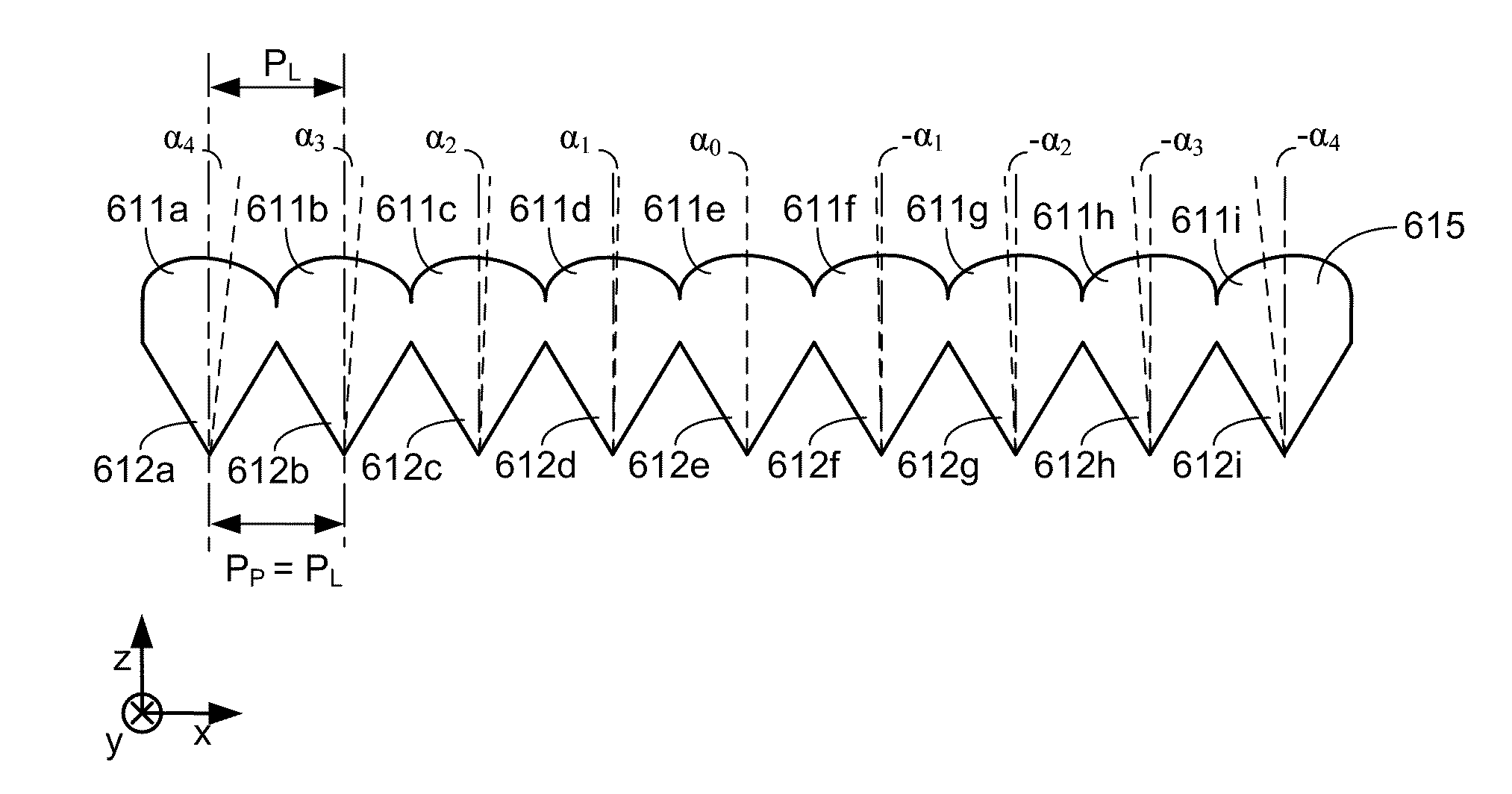
[0105]Optical film characteristics: Two sided optical film with cylindrical lenses on one surface and prisms on the opposing surface. Cylindrical lens radius of 36.3 microns; Cylindrical lens pitch of 52.0000 microns; Prism pitch of 52.0051 microns. FIG. 7B is a cross section showing various thicknesses of a two sided opti...
example 2
[0111]A display with an optical film having a-cylindrical lenses and varying prism pitch was simulated by ray tracing using TracePro. The display characteristics were the same as listed in Example 1 and are repeated below for reading convenience:
[0112]Display characteristics: WVGA (800×480 pixels); 196.8 mm (width)×118.08 mm (height); Viewing distance 750 mm, implying that the nominal eye separation of the viewer is + / −2.4 degrees. As illustrated in FIG. 7A, for viewer 710, the edge 722 of the display 720 is at an angle of 7.5 degrees from normal, assuming a display width of 196.4 mm and a viewing position of 750 mm above the display 720.
[0113]Optical film characteristics: A two sided optical film having a-cylindrical prisms on one surface and prisms on the opposing surface. The a-cylindrical lenses were designed for a stigmatic focus for this system. The lens had a varying radius of curvature, but at its vertex, the radius of curvature is 36.3 microns (the same as the cylindrical l...
example 3
[0118]A display with an optical film having rotated a-cylindrical lenses and constant prism pitch was simulated by ray tracing using TracePro. The display characteristics were the same as listed in Example 1 and are repeated below for reading convenience:
[0119]Display characteristics: WVGA (800×480 pixels); 196.8 mm (width)×118.08 mm (height); Viewing distance 750 mm, implying that the nominal eye separation of the viewer is + / −2.4 degrees. As illustrated in FIG. 7A, for viewer 710, the edge 722 of the display 720 is at an angle of 7.5 degrees from normal, assuming a display width of 196.4 mm and a viewing position of 750 mm above the display 720.
[0120]Optical film characteristics: A two sided optical film having a-cylindrical prisms on one surface and prisms on the opposing surface. The a-cylindrical lenses were designed for a stigmatic focus for this system. The lenses had a varying radius of curvature, but at its vertex, the radius of curvature is 36.3 microns (the same as the a-...
PUM
 Abstract
Description
Claims
Application Information
 - R&D
- Intellectual Property
- Life Sciences
- Materials
- Tech Scout
- Unparalleled Data Quality
- Higher Quality Content
- 60% Fewer Hallucinations
Browse by: Latest US Patents, China's latest patents, Technical Efficacy Thesaurus, Application Domain, Technology Topic, Popular Technical Reports.
© 2025 PatSnap. All rights reserved.Legal|Privacy policy|Modern Slavery Act Transparency Statement|Sitemap|About US| Contact US: help@patsnap.com


