Miniature receptacle terminals

a technology of receptacle terminals and terminals, applied in the direction of coupling device details, electrical discharge lamps, coupling device connections, etc., can solve the problems of inability to manufacture control, and inability to meet the requirements of manufacturing control, so as to minimize the variation of contact force. , good manufacturing control

Active Publication Date: 2014-03-04
MOLEX INC
View PDF7 Cites 26 Cited by
  • Summary
  • Abstract
  • Description
  • Claims
  • Application Information

AI Technical Summary

Benefits of technology

[0008]An embodiment of the present approach generally pertains to a mating section of a miniature receptacle terminal. The mating section of this embodiment has two primary contact beams and a single secondary beam augmenting the primary contact beams. The secondary beam is angled slightly more from the receptacle wall than is at least one of the primary contact beams such that the secondary beam contacts the primary contact beam in the unmated position. Each contact beam has a contact point opposing a contact bump on the opposing wall of the receptacle terminal. A distributed and balanced contact force is exerted on a male terminal pin that is inserted between the primary contact beams and the contact bumps. The dual contact beam component permits good manufacturing control and minimizes contact force variation among individual miniature receptacle terminals made according to this embodiment.
[0009]In another aspect of an embodiment of the miniature receptacle terminal, the dual contact beam spring contacts are secured from the rear of the mating section improving material efficiency. High terminal performance is obtained with low manufacturing cost.
[0010]In an additional aspect of an embodiment of the miniature receptacle terminal, the dual contact beam spring contacts are secured within a box shaped mating section protecting the spring contacts from damage that can be caused by the operating environment.
[0011]In a further embodiment or aspect of the miniature receptacle terminal, the mating section has an orientation member, a terminal front stop and primary and secondary lock up surfaces that assist in mounting the miniature terminal within a connector housing. The miniature receptacle terminal can be further secured by a terminal position assurance (“TPA”) member that can interact with a side of the receptacle terminal or with an end or front of the receptacle terminal. The orientation member can have a depression protecting the primary contact beams from overstress. Also, the miniature receptacle terminal can have a guide shield to assist in mating and to protect the mating pin from damage during insertion.

Problems solved by technology

Variation of tolerance due to multiple springs, however, often results in unacceptably large variations of contact force and manufacturing control is complicated.
Attempts have also been made to reinforce the thickness of the contact springs employing dimples or beads but this approach has also meet with limited success.

Method used


Image

  • Miniature receptacle terminals
  • Miniature receptacle terminals
  • Miniature receptacle terminals

Examples


Embodiment Construction

[0032]As required, detailed embodiments of the present invention are disclosed herein; however, it is to be understood that the disclosed embodiments are merely exemplary of the invention, which may be embodied in various forms. Therefore, specific details disclosed herein are not to be interpreted as limiting, but merely as a basis for the claims and as a representative basis for teaching one skilled in the art to variously employ the present invention in virtually any appropriate manner, including employing various features disclosed herein in combinations that might not be explicitly disclosed herein.

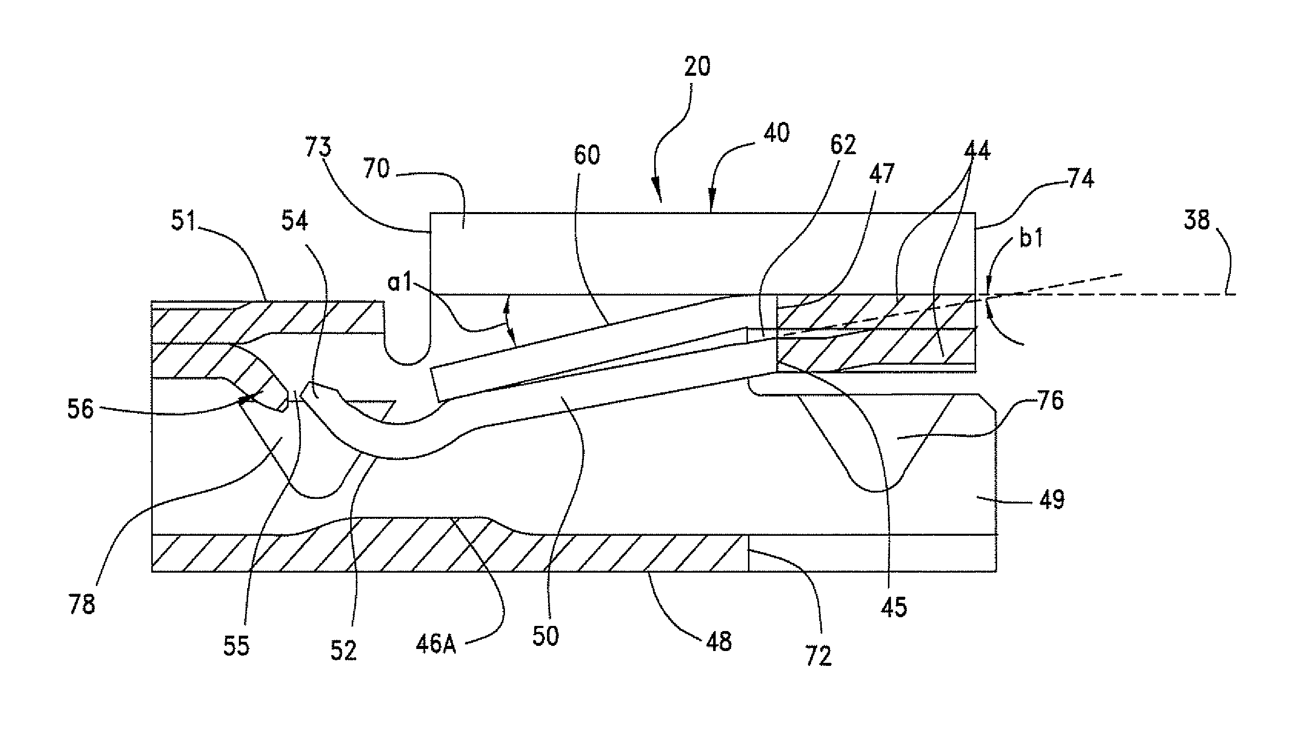
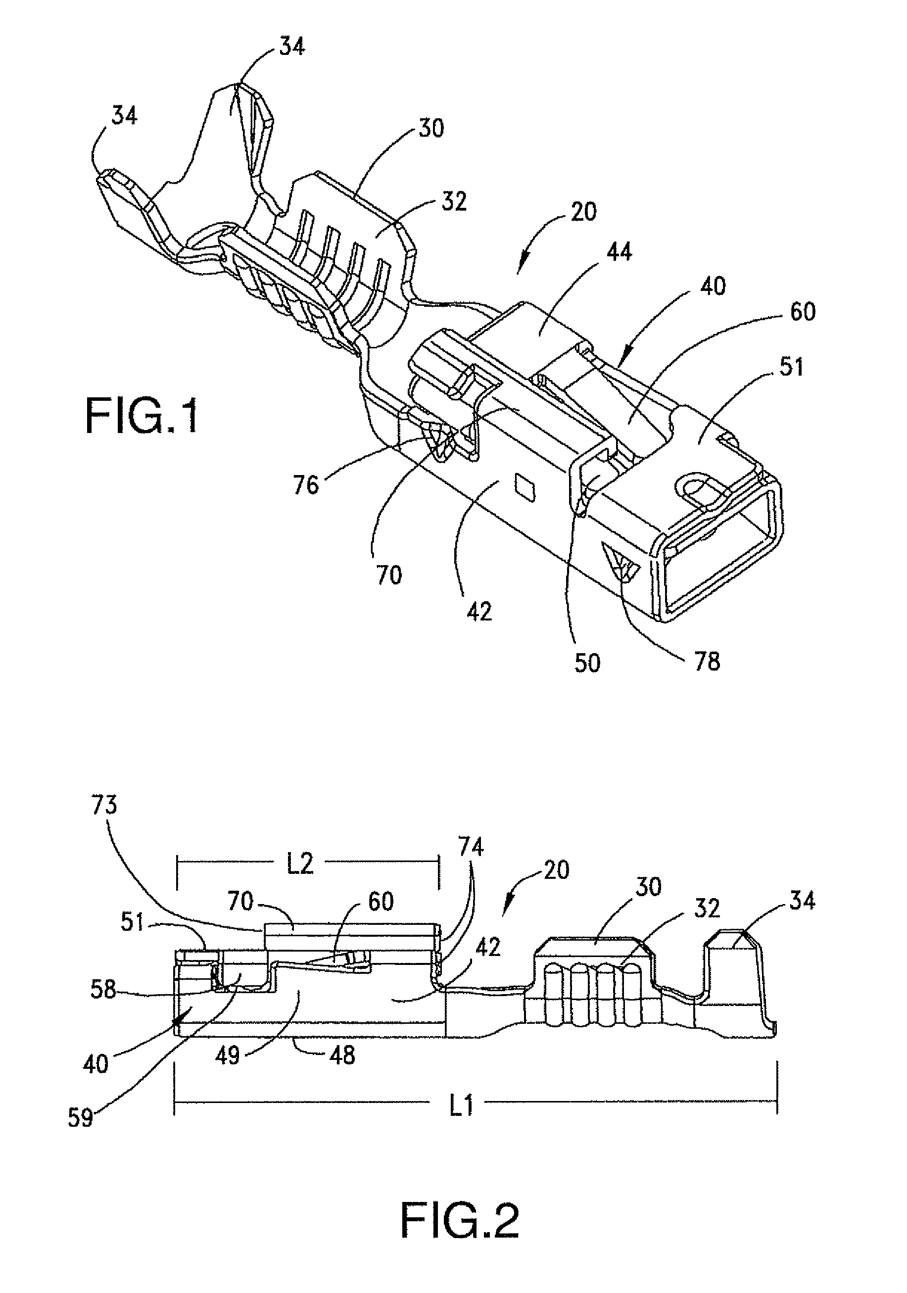
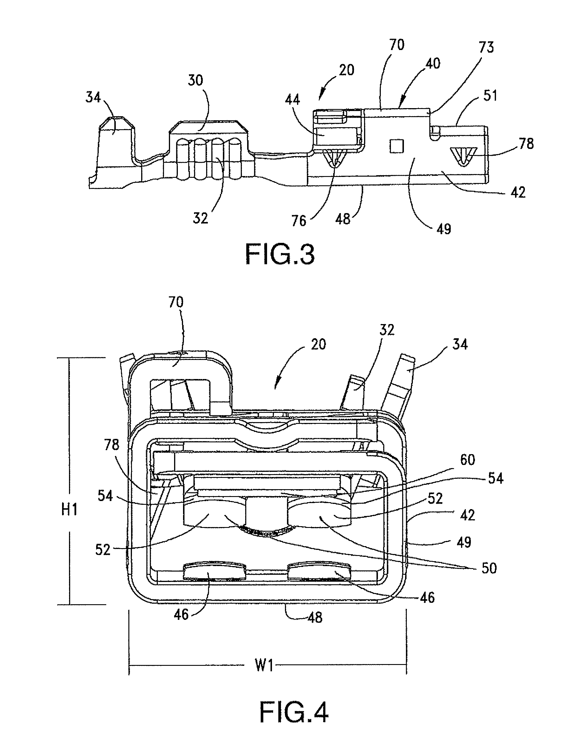
[0033]In an embodiment of this approach as shown in FIG. 1 through FIG. 7, miniature receptacle terminals, generally shown as 20, have a connection section 30 for connection to a conductor such as a wire conductor (not shown) and an opposing box-shaped mating section 40 for mating with a complementary male terminal (FIG. 7). Connection section 30 has sidewalls 32 for securely engagin...


PUM


Abstract

This approach generally pertains to a miniature receptacle terminal with a connection section and a mating section. The mating section has a dual primary contact beam component that includes contact springs having resilient contact beams and a secondary beam. Each contact beam has a contact point opposing the opposing wall of the receptacle terminal, which can include a contact bump. A distributed and balanced contact force is exerted on a male terminal pin that is inserted between the primary contact beams and the contact bumps. Overstress protection of the contact spring is provided and the terminal is economical to produce.

Description

BACKGROUND OF THE INVENTION[0001]This present invention generally pertains to receptacle terminals and more particularly to improved miniature receptacle terminals. These receptacle terminals are structured to enhance pin contact engagement or holding force.DESCRIPTION OF BACKGROUND ART[0002]The automotive market is shifting to downsized, small-footprint types of receptacle terminals. It is generally known that the contact engagement or holding force of receptacle terminals becomes weaker as the terminals become smaller since the contact springs become proportionally smaller. Attempts have been made to increase the contact engagement or holding force of smaller contact springs by stacking smaller contact springs together, for example, employing two contact springs together to double the combined spring thickness in an attempt to double the contact force. Variation of tolerance due to multiple springs, however, often results in unacceptably large variations of contact force and manuf...

Claims


Application Information

Patent Timeline
Patent Type & Authority Patents(United States)
IPC IPC(8): H01R24/00
CPCH01R13/113H01R13/193H01R13/4223H01R13/4361
Inventor JOUAS, VALERIEDUCLOS, JEAN-LOUIS
Owner MOLEX INC
Why Eureka
Try Eureka