

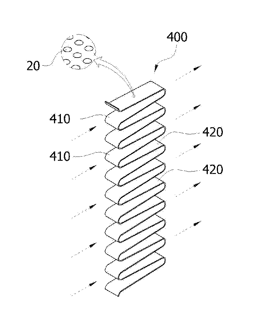
Strainer wall structure including curved sections
a curved section and strainer wall technology, applied in separation processes, nuclear elements, filtration separation, etc., can solve the problems of reducing filtering efficiency, easy deformation of single surface apparatus, and large increase in pressure drop at the screen, so as to increase the effective filtering area per unit time and simple structure
- Summary
- Abstract
- Description
- Claims
- Application Information
AI Technical Summary
Benefits of technology
Problems solved by technology
Method used
Image

Examples
Embodiment Construction
[0044]Various embodiments will now be described more fully with reference to the accompanying drawings in which some embodiments are shown. These inventive concepts may, however, be embodied in different forms and should not be construed as limited to the embodiments set forth herein. Rather, these embodiments are provided so that this disclosure is thorough and complete and fully conveys the inventive concept to those skilled in the art.
[0045]In the drawings, like reference numerals designate like elements throughout the invention.
Constitution and Structure of Strainer Wall Structure
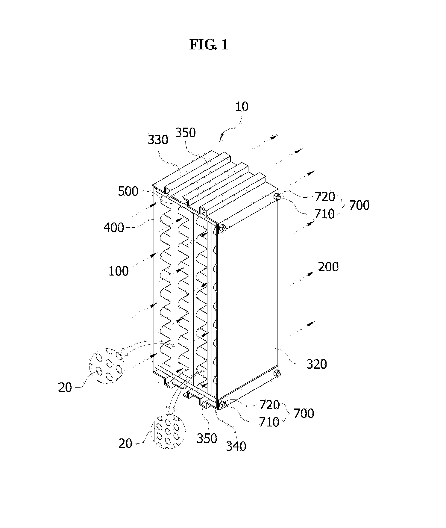
[0046]Hereinafter, a constitution and structure of a strainer wall structure 10 in accordance with an exemplary embodiment of the present invention will be described.
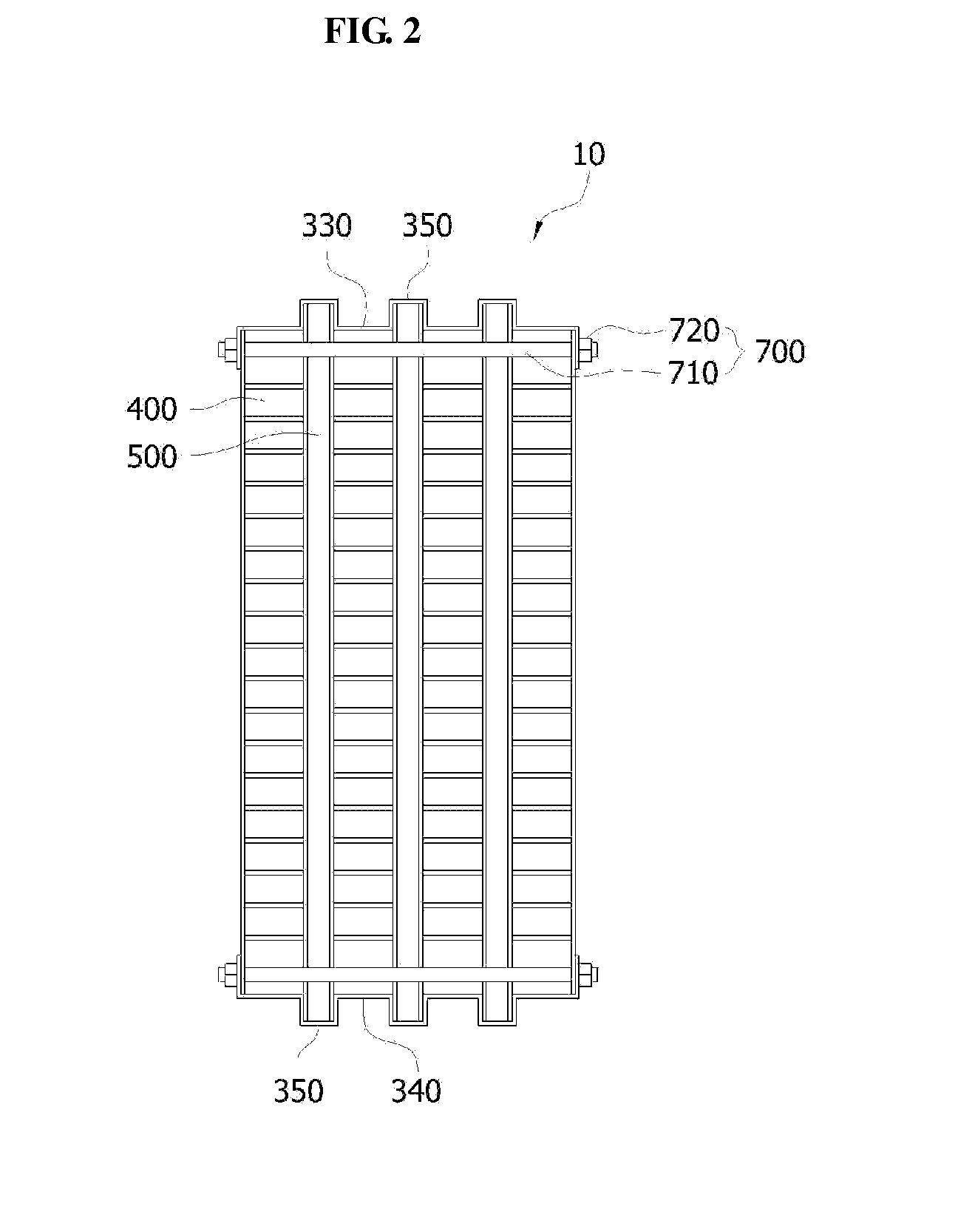
[0047]FIG. 1 is a perspective view of a strainer wall structure in accordance with an exemplary embodiment of the present invention, FIG. 2 is a front view of the strainer wall structure in accordance with an exemplary embodiment of the pre...
PUM
| Property | Measurement | Unit |
|---|---|---|
| diameter | aaaaa | aaaaa |
| width | aaaaa | aaaaa |
| width | aaaaa | aaaaa |
Abstract
Description
Claims
Application Information