Server rack

a server rack and rack technology, applied in the field of server racks, can solve the problems of inability to quickly detach and maintain, and achieve the effect of improving assembly/disassembly and maintenance convenien

Inactive Publication Date: 2014-03-04
INVENTEC CORP
View PDF15 Cites 8 Cited by
  • Summary
  • Abstract
  • Description
  • Claims
  • Application Information

AI Technical Summary

Benefits of technology

[0024]According to the above descriptions, the fan case is detachably assembled to the back surface side of the rack body and is electrically connected to the rack body independently, and each of the fan units is detachably assembled to the fan case and is electrically connected to the fan case independently. In this way, the fan case can be independently detached from the rack body to implement hot-plugging, and each of the fan units can be independently detached from the fan case to implement hot-plugging. When the fan case or the fan unit is independently detached or hot-plugged, operations of the other fan units are not influenced, so that assembling / disassembling and maintenance convenience are improved.

Problems solved by technology

Generally, fans of the conventional rack mount server are not independently assembled to a rack respectively, which is of no avail for quick detaching and maintenance.
Moreover, the fans of the conventional rack mount server are not electrically connected to the rack independently, and independent hot-plug thereof cannot be implemented, so that when a single fan is repaired, the other fans are all stopped, which causes inconvenience.

Method used


Image

  • Server rack
  • Server rack
  • Server rack

Examples


Embodiment Construction

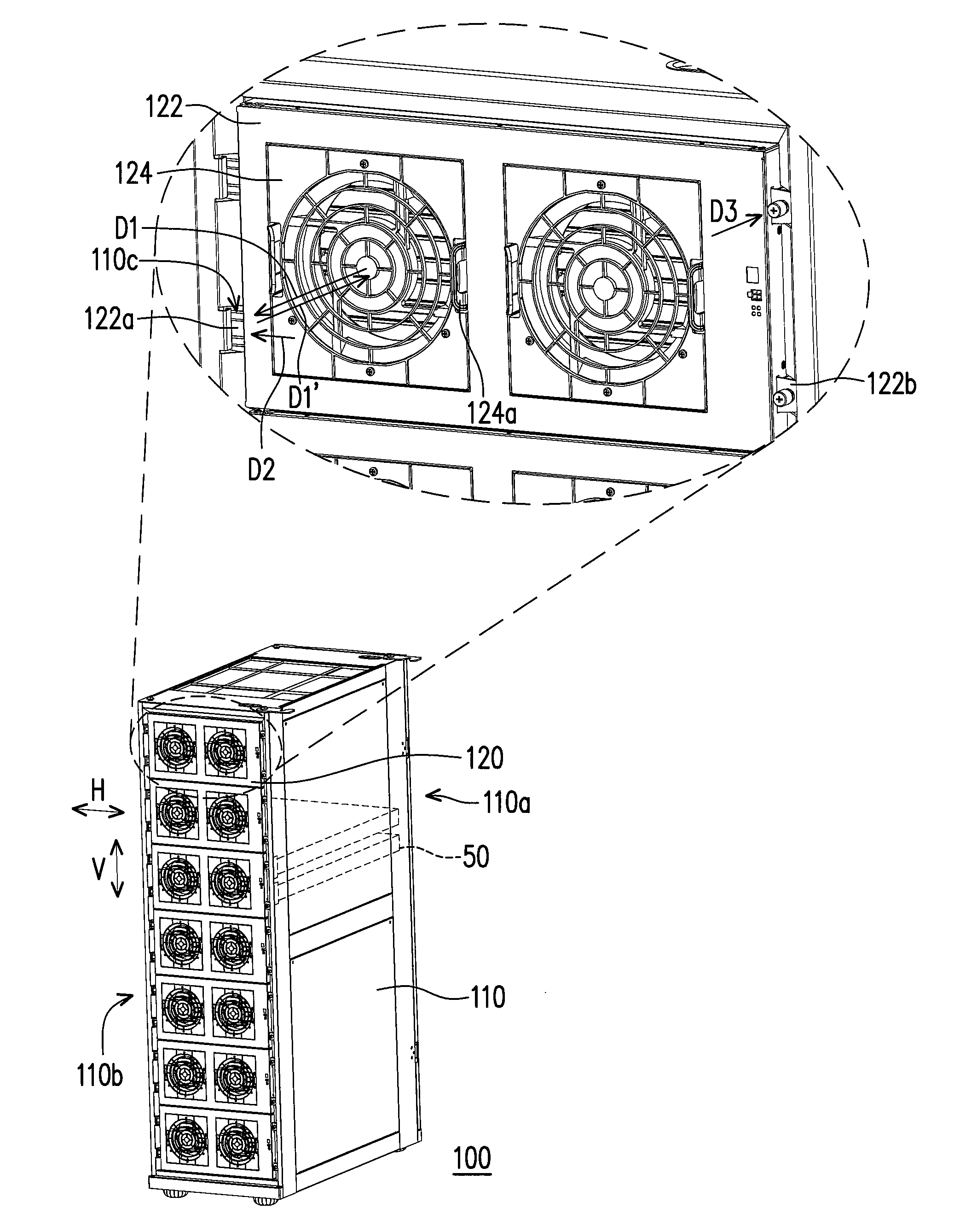
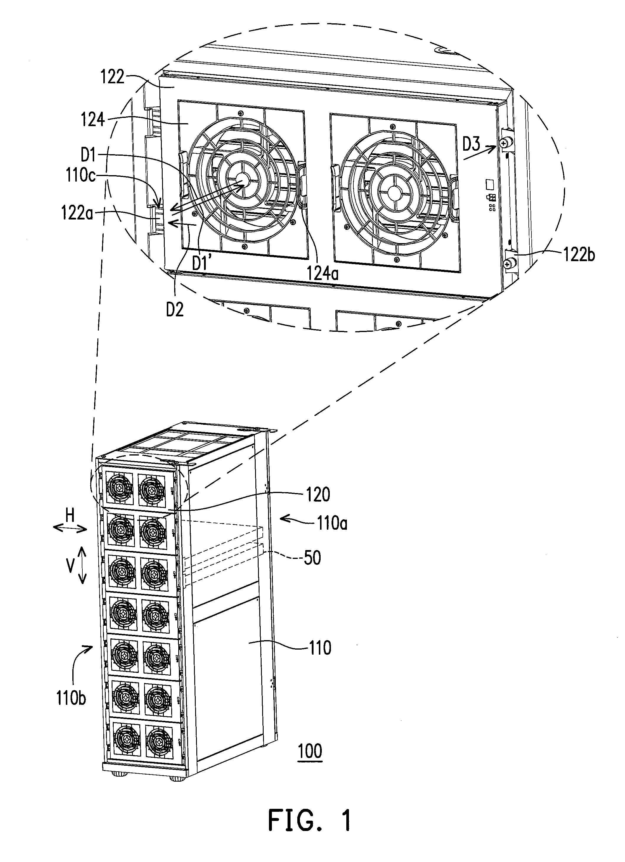
[0037]FIG. 1 is a three-dimensional view of a server rack according to an embodiment of the invention. Referring to FIG. 1, the server rack 100 of the embodiment includes a rack body 110 and a plurality of fan modules 120. A plurality of server units 50 are disposed in the rack body 110 (only two server units 50 are schematically illustrated). The rack body 110 has a front side 110a and a back side 110b opposite to each other. The fan modules 120 are arranged on the back side 110b of the rack body 110 along a vertical direction V. Each of the fan modules 120 is aligned to several of the server units 50 (only two server units 50 are schematically illustrated), so as to dissipate heat generated by the server units 50 or other components in the server rack 100.

[0038]In detail, each of the fan modules 120 includes a fan case 122 and a plurality of fan units 124 (two fan units are schematically illustrated). The fan case 122 is detachably assembled to the back side 110b of the rack body ...


PUM


Abstract

A server rack includes a rack body and fan modules. The rack body has front and back surfaces. Server units are disposed in the rack body. The fan modules are arranged on the back side along a vertical direction. Each fan module corresponds to several server units and includes a fan case and fan units. The fan case assembled to the back side is independently electrically connected to the rack body and suitable for being independently detached from the rack body. The fan units are detachably assembled to the fan case and arranged on the fan case along a horizontal direction. Each fan unit is independently electrically connected to the fan case and suitable for being independently detached from the fan case along a first direction perpendicular to the back surface or independently assembled to the fan case along a second direction opposite to the first direction.

Description

CROSS-REFERENCE TO RELATED APPLICATION[0001]This application claims the priority benefit of Taiwan application serial no. 201110267856.1, filed Sep. 8, 2011. The entirety of the above-mentioned patent application is hereby incorporated by reference herein and made a part of this specification.BACKGROUND OF THE INVENTION[0002]1. Field of the Invention[0003]The invention relates to a server rack. Particularly, the invention relates to a server rack including fan units.[0004]2. Description of Related Art[0005]A server is a core computer in a network system used for serving various computers, which can provide functions such as storage and print service for network users, and provide clients to share various resources within the network environment. A basic structure of the server is approximately the same to a general personal computer, which is composed of a central processing unit (CPU), a memory and an input / output (I / O) device, etc., and the devices are connected through a bus. A n...

Claims


Application Information

Patent Timeline
Patent Type & Authority Patents(United States)
IPC IPC(8): H05K7/20G06F1/20
CPCH05K7/20736
Inventor WANG, SHI-FENG
Owner INVENTEC CORP
Why Eureka
Try Eureka