Method of supporting drywall

a technology of supporting tools and drywall, which is applied in the field of drywall, can solve the problems of tiring and awkward fastening of sheets to horizontal, vertical or angular studs, joists, rafters or trusses, and many though are cumbersome and expensive, and large and cumbersome in its siz

Inactive Publication Date: 2014-03-11
MCCARTHY JENNIFER M
View PDF36 Cites 33 Cited by
  • Summary
  • Abstract
  • Description
  • Claims
  • Application Information

AI Technical Summary

Benefits of technology

[0020]Applicant has disclosed a method and device (i.e., tool) for supporting sheathing (e.g., drywall) prior to securing the sheathing to, for example, stud boards or rafters. In the preferred “device” embodiment, Applicant's tool is generally “J”-shaped with four short tapered spikes (brads or “teeth”) on its backside. By hammering the front of the tool, its teeth can be driven into the underlying structure, e.g., the wall stud. That firmly locks the tool in place without the need for separate nails or screws. Then a user can place one corner of the sheathing into a lipped bottom of the tool, where it is supported until the sheathing is secured (e.g., nailed or screwed) to the underlying structure.

Problems solved by technology

Due to the size and weight of these sheet materials, fastening of the sheets to horizontal, vertical, or angular studs, joists, rafters or trusses can be tiring and awkward, especially when only one or two installers are on the job site.
Many though are cumbersome and expensive.
It is generally fabricated on the job site to accommodate a specific height dimension, is large and cumbersome in its size, and is not easily transported from one job site to the next.

Method used


Image

  • Method of supporting drywall
  • Method of supporting drywall

Examples


embodiment 100

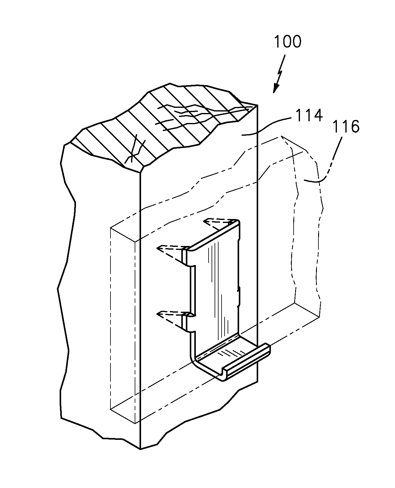
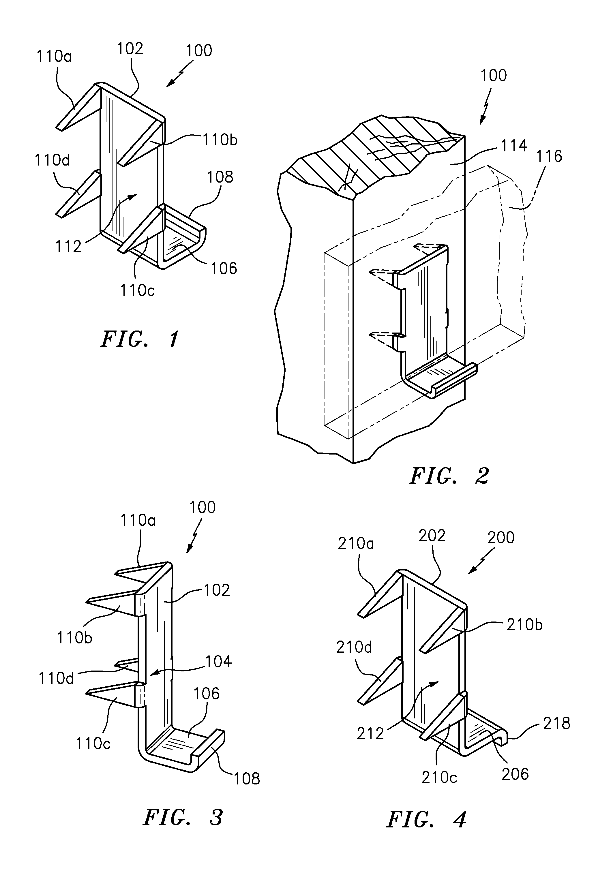
[0027]FIGS. 1-3 depict a preferred embodiment 100 of the “STUD HUGGER”. As shown, Applicant's preferred device 100 is generally “J”-shaped. It is preferably made of metal, but could be made in plastic.

[0028]The preferred embodiment 100 comprises: a vertical stem 102 having a flat front side 104; a flat bottom 106, integral with and substantially perpendicular to the stem 102; and an upturned lip 108, integral with the bottom 106 and substantially parallel to stem 102. While the preferred lip is substantially perpendicular to the bottom 104, it alternatively can be an acute angle relative to bottom 106. Tapered spikes (a.k.a. brads or teeth) 110a, 110b, 110c, 110d are integral with and protrude from a backside 112 of the stem 102. The spikes are equally spaced apart, with: spikes 110a, 110d at one edge of the backside 112; spikes 110b, 110c at another edge of the backside; and spikes 110a, 110b adjacent respective corners of the backside. Upon hammering the spikes 110a, 110b, 110c, 1...

embodiment 200

[0031]FIG. 4 depicts an alternate embodiment 200 of the STUD HUGGER. Its structure is virtually identical to the preferred embodiment. Identical elements in FIG. 4 have the prefix 200. For example, the vertical stem 102 in FIGS. 1-3 is denoted by 202 in FIG. 4. The only difference between the two embodiments is the lip 218 is downturned, not upturned, in FIG. 4.

[0032]Applicant's invention can be thought of as a method of temporarily supporting drywall comprising the following sequential steps:[0033]a. hammering a flat front side of a vertical stem of a (preferably J-shaped) support tool to drive a plurality of spikes on a backside of the stem into a wall stud, whereby the tool is locked in place without having to use any nail or screw;[0034]b. supporting a drywall sheet within a lipped shelf of the tool, wherein a flat portion of the shelf is integral with, and extends substantially perpendicular to, one end of the stem; and[0035]c. attaching the entire drywall sheet to the wall stu...


PUM


Abstract

Applicant has disclosed a method and device (i.e., support tool) for installing sheathing (e.g., drywall or plasterboard). This tool enables a single person to easily attach the sheathing (e.g., by nails or screws) to an underlying structure (e.g., a wall stud, joist or rafter). In the preferred “device” embodiment, Applicant's tool is generally J-shaped with four tapered spikes (“teeth”) on its backside. The spikes are equally spaced from one another. By hammering the tool, its spikes can be driven into the underlying structure. No separate nail or screw is needed to hold the tool in place.

Description

FIELD OF INVENTION[0001]The present invention relates generally to sheathing (e.g., drywall) used in building constructions. More particularly, it relates to support tools for fastening sheathing.BACKGROUND OF THE INVENTION[0002]Sheet materials (a.k.a. sheathing), such as drywall and Sheetrock® plasterboard, are commonly used in residential, commercial and industrial buildings for covering walls or ceilings. The sheets are manufactured in standard sizes, such as 4×8 feet or 4×12 feet. Due to the size and weight of these sheet materials, fastening of the sheets to horizontal, vertical, or angular studs, joists, rafters or trusses can be tiring and awkward, especially when only one or two installers are on the job site.[0003]Various devices have been used to temporarily support the sheets before attaching them to the underlying structures such as wall studs or roof rafters. They usually are designed to allow one installer to do the job. Many though are cumbersome and expensive. Others...

Claims


Application Information

Patent Timeline
Patent Type & Authority Patents(United States)
IPC IPC(8): E04B2/70
CPCE04F13/0828E04F13/0841F16B15/02F16B15/00E04B2/70E04B2/7457E04B2002/7477
Inventor MCCARTHY, JENNIFER, M.
Owner MCCARTHY JENNIFER M
Why Eureka
Try Eureka