Chair with tilting backrest

a backrest and chair technology, applied in the field of chairs with tilting backrests, to achieve the effect of simple and inexpensive structur

Inactive Publication Date: 2014-03-11
PRO CORD SPA
View PDF13 Cites 15 Cited by
  • Summary
  • Abstract
  • Description
  • Claims
  • Application Information

AI Technical Summary

Benefits of technology

[0008]The object of the present invention is to provide a chair with tilting backrest with an elastically deformable joint that connects the backrest to the supporting structure of the chair, where the joint is provided with an end-of-travel that limits the inclination backwards of the backrest having a simple and inexpensive structure.

Problems solved by technology

The chief drawback of the solution described in the document No.

Method used


Image

  • Chair with tilting backrest
  • Chair with tilting backrest
  • Chair with tilting backrest

Examples


second embodiment

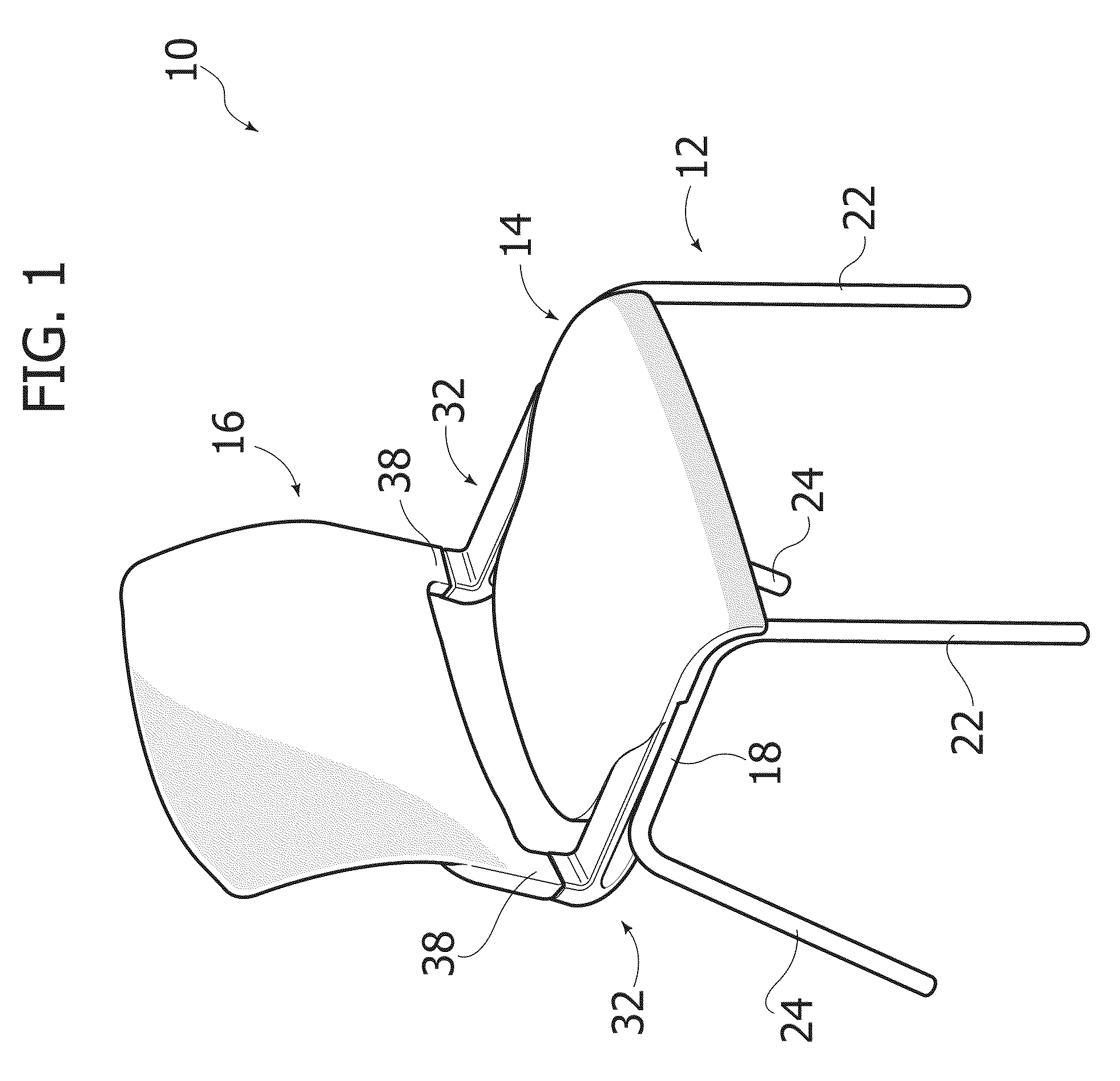
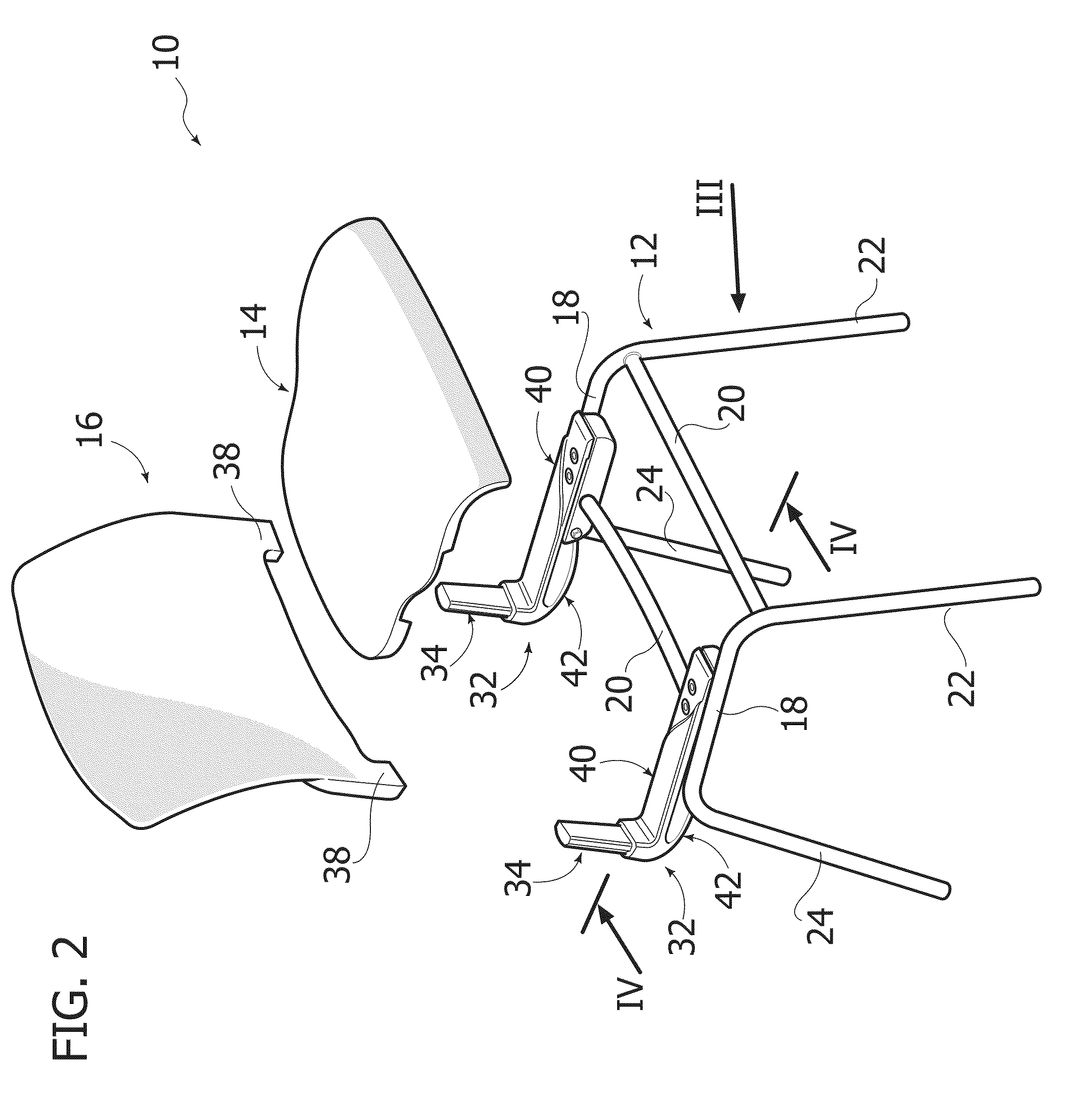
[0034]FIG. 9 illustrates a chair according to the invention. The elements corresponding to the ones described previously are designated by the same reference numbers.

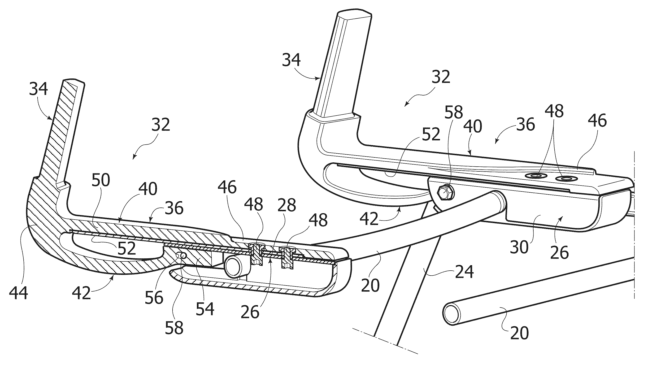
[0035]In the variant of FIG. 9, the second connection portions 36 of the joints 32 are formed integrally with the seat 14. More precisely, the first arms 40 of the joints 32 are formed by elastically deformable lateral portions of the seat 14 that project in cantilever fashion towards the rear part. The second arms 42 of the joints 32 are formed as described previously. The second connection portions 36 of the joints 32 are connected to the basic structure 12 via the seat 14.

[0036]As in the embodiment described previously, the first connection portions 34 of the joints 32 can be formed integrally with the bottom lateral portions of the backrest 16, or else the first connection portions 34 can be inserted and fixed within respective bottom lateral portions 38 of the backrest 16.

third embodiment

[0037]Illustrated in FIGS. 10 and 11 is a chair according to the invention. The elements corresponding to the ones described previously are designated by the same reference numbers.

[0038]In the embodiment of FIGS. 10 and 11, the seat 14 and the backrest 16 are formed by a flexible canvas 60, the lateral edges of which are anchored to respective lateral supports formed by the joints 32. In particular, the first connection portions 34 of the joints 32 form two uprights, anchored to which are the lateral edges of the portion of canvas 60 forming the backrest 16, and the first arms 40 of the joints 32 form two horizontal supports, anchored to which are the lateral edges of the portion of canvas 60 forming the seat 14. The second arms 42 of the second connection portions 36 are made as described previously with reference to FIGS. 1-3.

[0039]The first connection portions 34 extend substantially throughout the height of the backrest 16, and the first arms 40 of the second connection portion...


PUM


Abstract

A chair comprising a basic structure, a seat, a backrest, and at least one joint made of plastic material, which connects the backrest to the basic structure, wherein the joint has a first connection portion fixed to or integral with respect to the backrest, and a second connection portion connected to the basic structure, wherein said second connection portion comprises a first and a second arm, which are elongated in a longitudinal direction and are set at a distance from one another in a vertical direction, wherein the first arm has a front portion fixed to the basic structure and is deformable between a resting position corresponding to the resting position of the backrest and a deformed position corresponding to the position where the backrest is tilted backwards, wherein the second arm has a front portion, which is mobile in a longitudinal direction with respect to the basic structure between a first position corresponding to the resting position of the first arm, and a second position corresponding to the deformed position of the first arm, and wherein the second arm and the basic structure are provided with respective arrest elements which limit the extent of the travel in a longitudinal direction of the front portion of the second arm and define an end-of-travel of tilting backwards of the backrest.

Description

CROSS-REFERENCE TO RELATED APPLICATIONS[0001]This application claims benefit of European patent application serial number 10425237.4, filed Jul. 15, 2010, which is herein incorporated by reference.BACKGROUND OF THE INVENTION[0002]1. Field of the Invention[0003]The present invention relates to a chair with tilting backrest.[0004]More precisely, the invention regards a chair comprising a basic structure, a seat carried by the basic structure, a backrest, and at least one joint made of plastic material that connects the backrest to the basic structure, wherein the joint has a first connection portion fixed or integral with respect to the backrest, and a second connection portion connected to the basic structure, and wherein the joint is elastically deformable to enable a movement of the backrest between a resting position and a position tilted backwards under a thrust backwards applied by the user.[0005]2. Description of the Related Art[0006]The document No. EP-A-1557115 filed in the n...

Claims


Application Information

Patent Timeline
Patent Type & Authority Patents(United States)
IPC IPC(8): A47C3/00A47C1/024
CPCA47C7/445A47C1/024
Inventor PIRETTI, ALESSANDRO
Owner PRO CORD SPA
Why Eureka
Try Eureka