Resin molding method, die device, and resin molded article

a technology die devices, which is applied in the field of resin molded objects, can solve the problems of not being able to eliminate the disturbed flow of resin, and achieve the effect of high-grade metallic appearan

Inactive Publication Date: 2014-03-11
PANASONIC CORP
View PDF12 Cites 0 Cited by
  • Summary
  • Abstract
  • Description
  • Claims
  • Application Information

AI Technical Summary

Benefits of technology

[0014]In the resin molding methods of Japanese Patent Laid-Open No. 8-72067 and Japanese Patent Laid-Open No. 2000-301583 of the related art, uneven portions that may interfere with a flow or a split flow of resin in the flowing paths of molten resin into the cavities 125 and 133 are eliminated in the cavities 125 and 133, thereby preventing disturbed resin flows leading to welds or orientation lines in a resin flow pattern on the design surface.
[0017]The present invention has been devised to solve the problems of the related art. An object of the present invention is to provide a resin molding method, a die device, and a resin molded article which can obtain a high-grade appearance without forming welds or orientation lines in a resin flow pattern on a design surface, even in the case where a cavity has a projecting die portion that may split or interfere with a flow of molten resin in a path of the molten resin in the cavity.
[0020]According to this method, even in the case where welds or orientation lines in a flow pattern occur at the junction of resin flowing into the cavity, the flow gates are retracted afterward to allow the resin at the joint to flow into the restricted area, thereby preventing welds and orientation lines in a resin flow pattern from occurring outside the restricted area. Even in the case where a resin molded article has an uneven portion and a die cavity includes a projecting portion or a recessed portion corresponding to the uneven portion, welds or orientation lines in a resin flow pattern occur only at the uneven portions of the resin molded article and are prevented from occurring on the design surface of the resin molded article. Further, the temperature of at least the die surface facing the cavity is increased to at least the glass transition temperature of the resin, thereby preventing welds at the joint of resin flowing into the cavity.
[0029]The resin molding method of the present invention can achieve a high-grade metallic appearance without forming welds or orientation lines in a resin flow pattern on the design surface of an exterior component, the resin molding method eliminating the need for subsequent treatment such as painting.

Problems solved by technology

Thus in the resin molding method, in the case where a path in the cavity containing molten resin flowing along the design surface 111 has a recessed portion or a projecting portion (uneven portion) that may interfere with a flow or a split flow of resin, it is not possible to eliminate a disturbed flow of the resin to prevent welds and orientation lines in a resin flow pattern.
Further, in the case where a product has a recessed portion interfering with a resin flow, that is, a die has a projecting portion, a resin flow is blocked and thus results in welds or orientation lines in a resin flow pattern on the design surface 111.

Method used


Image

  • Resin molding method, die device, and resin molded article
  • Resin molding method, die device, and resin molded article
  • Resin molding method, die device, and resin molded article

Examples


first embodiment

(First Embodiment)

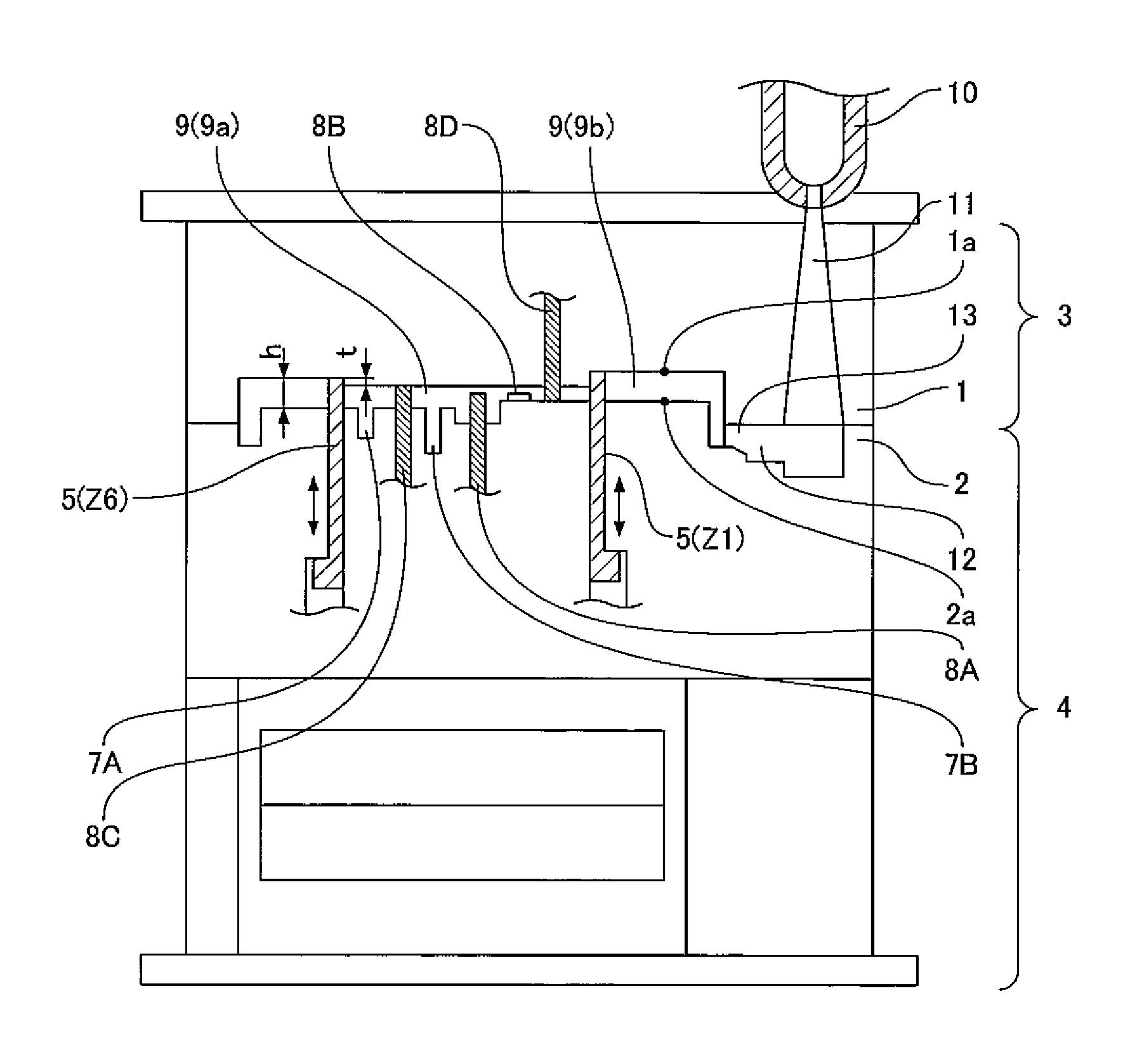
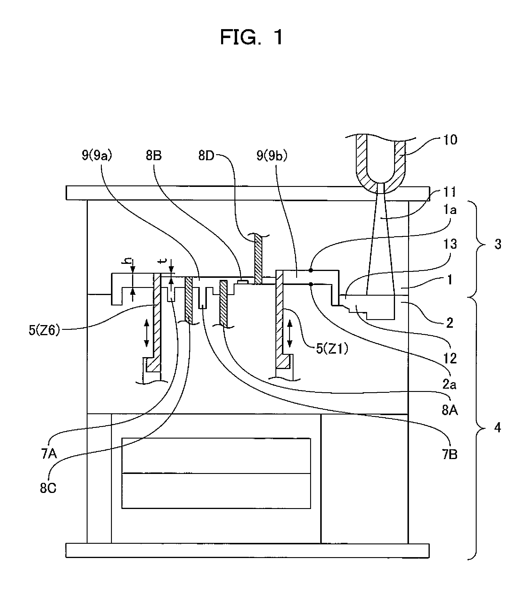
[0051]FIG. 1 is a front sectional view showing a die device used for a resin molding method according to a first embodiment of the present invention. FIG. 2 is a plan view showing a movable die according to the first embodiment. FIG. 3 shows front sectional views of the schematic steps of the resin molding method according to the first embodiment. FIG. 4 is a perspective view showing a resin molded article fabricated by the resin molding method according to the first embodiment of the present invention. FIG. 5 is a perspective view showing a resin molded article according to the related art. FIGS. 6A, 6B, and 7 are plan views showing the movable die in the steps of the resin molding method according to the first embodiment.

[0052]Referring to FIG. 4, the following will first describe the resin molded article fabricated by the resin molding method according to the first embodiment of the present invention.

[0053]Reference numeral 20 in FIG. 4 denotes the resin molded ...

second embodiment

(Second Embodiment)

[0087]Referring to FIGS. 9 to 11B and 4, 7, and so on, the following will describe a resin molding method and a resin molded article according to a second embodiment of the present invention. Constituent elements having the same functions as in the first embodiment will be indicated by the same reference numerals and the explanation thereof is omitted.

[0088]FIG. 9 is a front sectional view showing a die device used for the resin molding method and FIG. 10 is a plan view showing a movable die according to the second embodiment of the present invention. FIGS. 11A and 11B are plan views showing the movable die (the cavity of the movable die) in the steps of the resin molding method according to the second embodiment.

[0089]As shown in FIGS. 9, 10, 11A, and 11B, in the die device used for the resin molding method according to the second embodiment, flow gates 5 capable of protruding and retracting are disposed as in the die device used for the resin molding method acco...


PUM

PropertyMeasurementUnit
temperatureaaaaaaaaaa
glass transition temperatureaaaaaaaaaa
widthaaaaaaaaaa

Abstract

Flow gates 5 capable of protruding and retracting are provided in a cavity 9 of a die 2 to control a resin filling path. The generation of welds or orientation lines in a resin flow pattern is allowed only in an area containing uneven portions outside a design surface but is not allowed in other areas. The area containing welds or orientation lines in a resin flow pattern is covered with a separate component having a design surface, thereby achieving a desired metallic appearance.

Description

FIELD OF THE INVENTION[0001]The present invention relates to resin molding methods for obtaining resin molded articles such as resin exterior components having design surfaces, and particularly relates to a resin molding method for obtaining a high-grade metallic appearance without forming welds or orientation lines in a resin flow pattern on a design surface, a die device used for the resin molding method, and a resin molded article obtained by the resin molding method.BACKGROUND OF THE INVENTION[0002]For example, Japanese Patent Laid-Open No. 2008-49652 proposes a resin molding method for obtaining a high-grade metallic appearance according to the related art, in which welds or orientation lines in a resin flow pattern are not formed on a design surface by glittering materials containing metallic compounds including aluminum, mica, and glass flakes. The technique of the resin molding method prevents a flow of molten resin into a cavity between dies from first reaching a shape affe...

Claims


Application Information

Patent Timeline
Patent Type & Authority Patents(United States)
IPC IPC(8): B29C45/56B29C45/73
CPCB29C2045/7356B29C45/0025B29C45/0046Y10T428/24479Y10T428/24273
Inventor MATSUMURA, KEIZOUMARUICHI, TAISHI
Owner PANASONIC CORP
Why Eureka
Try Eureka