Wireless power feeder, wireless power receiver, and wireless power transmission system
a wireless power feeder and wireless power technology, applied in the direction of transformer/inductance details, transformer/inductance circuit, inductance, etc., can solve the problems of complex control circuit and system, increase in the number of components, etc., to suppress the decline in the resonance current, suppress the decline in the q value, and restrict the power transmission efficiency of the wireless power feeder
- Summary
- Abstract
- Description
- Claims
- Application Information
AI Technical Summary
Benefits of technology
Problems solved by technology
Method used
Image
Examples
first embodiment
[First Embodiment]
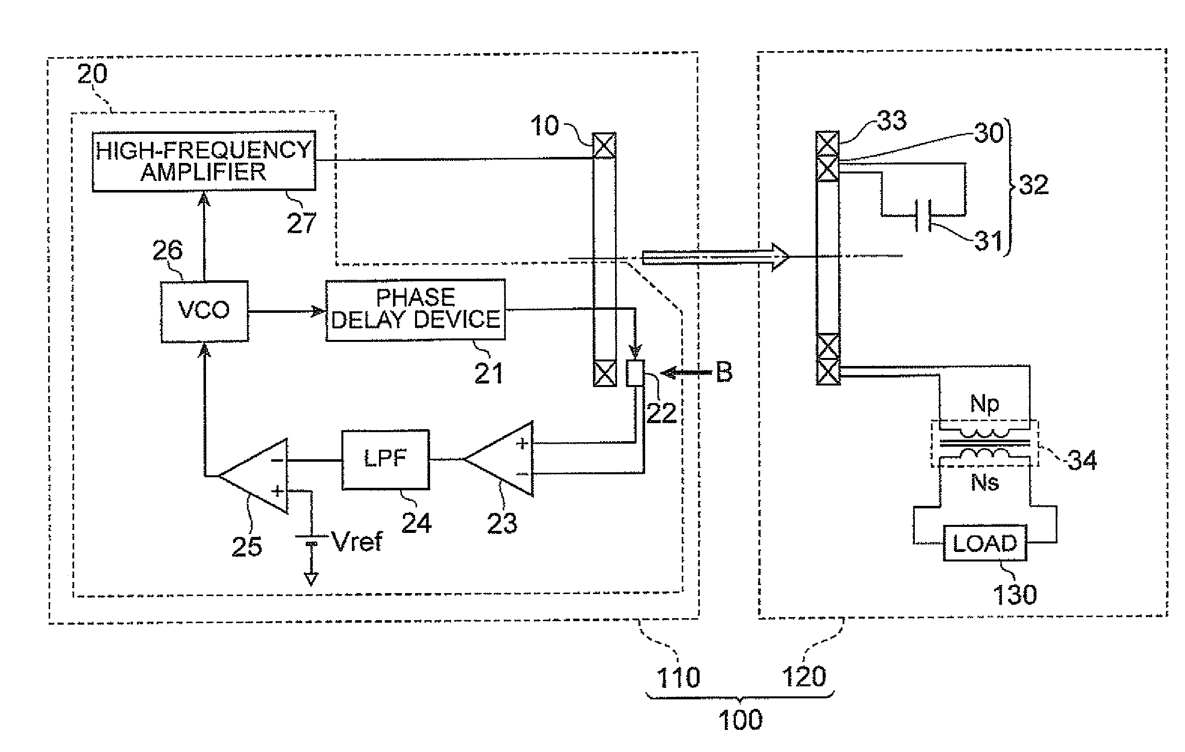
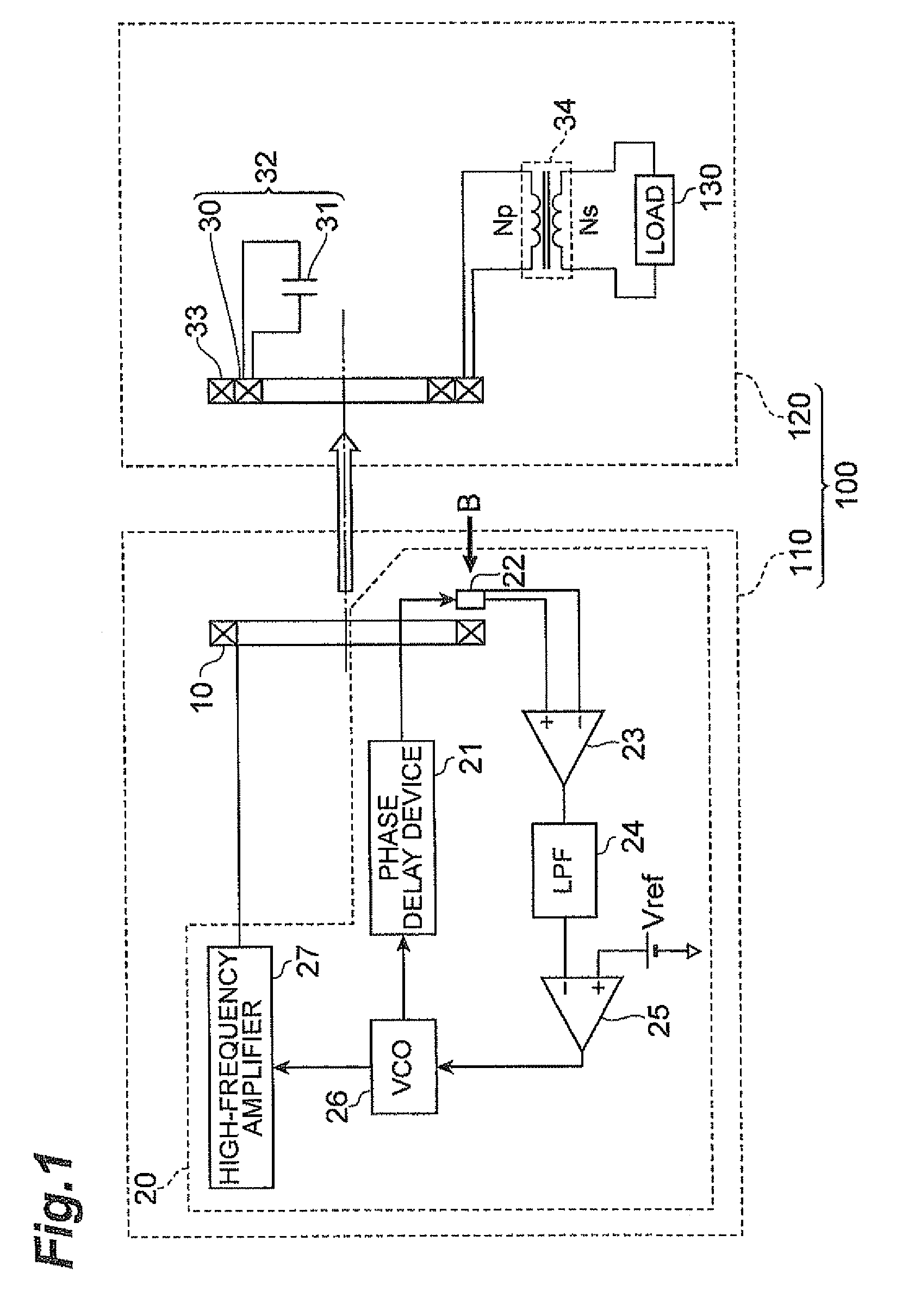
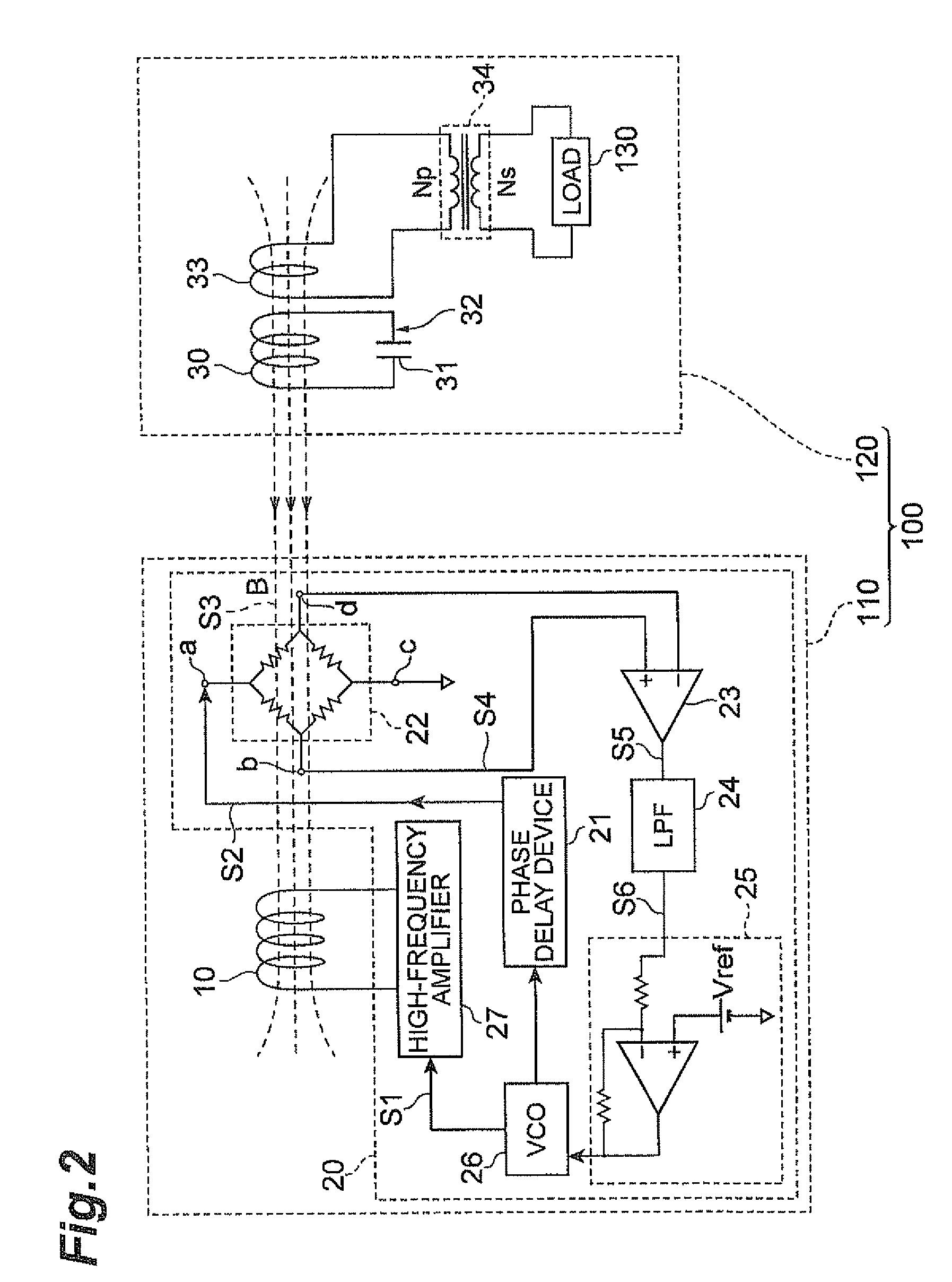
[0056]FIG. 2 is a diagram showing the electrical composition of a wireless power transmission system relating to a first embodiment of the present invention. The wireless power transmission system 100 shown in FIG. 2 comprises a wireless power feeder 110 and a wireless power receiver 120, and performs power transmission by a non-contact method from the wireless power feeder 110 to the wireless power receiver 120.
[0057]The wireless power feeder 110 comprises a power feed coil 10 and a control circuit 20. On the other hand, the wireless power receiver 120 comprises a power receive resonance circuit 32 comprising of a power receive coil 30 and a power receive capacitor 31.
[0058]In the wireless power feeder 110, the control circuit 20 supplies an AC current (for example, a square wave or sinusoidal wave current) to the power feed coil 10, whereby power is supplied from the power feed coil 10 to the power receive coil 30 on the basis of a magnetic field resonance effect...
second embodiment
[Second Embodiment]
[0090]In the first embodiment, a wireless power transmission system 100 in which the wireless power feeder 110 side does not resonate was given as an example, but a wireless power transmission system which comprises two resonance circuits, a power feed resonance circuit and a power receive resonance circuit, is not excluded from the scope of the present invention.
[0091]FIG. 11 is a diagram showing an electrical composition of a wireless power feeder in a wireless power transmission system relating to the second embodiment of the present invention, and FIG. 10 is a cross-sectional diagram showing a schematic view of the physical structure of the power feed coil 10, the magnetic sensor 22, the power receive coil 30 and the power receive load coil 33 shown in FIG. 11. FIG. 10 shows the electrical composition of the peripheral circuit elements of these coils.
[0092]The wireless power transmission system 100A according to the second embodiment comprises a wireless power...
third embodiment
[Third Embodiment]
[0094]In the second embodiment, a wireless power feeder 110A which comprises just one magnetic sensor 22 was given as an example, but it may also comprise a plurality of magnetic sensors 22.
[0095]FIG. 9 is a diagram showing the electrical composition of a wireless power feeder relating to a third embodiment of the present invention. In this way, the wireless power feeder 110B differs from the second embodiment in respect of comprising a control circuit 20B instead of the control circuit 20 in the wireless power feeder 110A. The control circuit 20B comprises eight magnetic sensors 22 instead of the magnetic sensor 22, in the control circuit 20, and also comprises an adder 28.
[0096]The magnetic sensors 22 are arranged equidistantly, 45° apart respectively, over the winding circumference of the power feed coil 10. The magnetic sensors 22 are respectively connected to the adder 28. The adder 28 adds the output voltages of the eight magnetic sensors 22 and outputs the r...
PUM
| Property | Measurement | Unit |
|---|---|---|
| power factor | aaaaa | aaaaa |
| frequency | aaaaa | aaaaa |
| AC voltage | aaaaa | aaaaa |
Abstract
Description
Claims
Application Information
 - R&D
- Intellectual Property
- Life Sciences
- Materials
- Tech Scout
- Unparalleled Data Quality
- Higher Quality Content
- 60% Fewer Hallucinations
Browse by: Latest US Patents, China's latest patents, Technical Efficacy Thesaurus, Application Domain, Technology Topic, Popular Technical Reports.
© 2025 PatSnap. All rights reserved.Legal|Privacy policy|Modern Slavery Act Transparency Statement|Sitemap|About US| Contact US: help@patsnap.com


