Wireless power transmission device and vehicle

a transmission device and wireless technology, applied in the direction of electric devices, charging stations, transportation and packaging, etc., can solve the problems of affecting the transmission efficiency of electric vehicles, so as to achieve the effect of constant efficient wireless power transmission

Active Publication Date: 2016-01-14
IHI CORP
View PDF12 Cites 7 Cited by
  • Summary
  • Abstract
  • Description
  • Claims
  • Application Information

AI Technical Summary

Benefits of technology

[0018]According to the present disclosure, because a power-supplying coil configured to form an electromagnetic coupling circuit along with a power-receiving coil provided in an EV that is a power supply target to which power should be supplied is installed in a slanted state or perpendicularly to a horizontal plane, a metallic foreign object on an upper surface of the power-supplying coil slides down due to gravity. Thereby, it is possible to constantly perform efficient wireless power transmission by preventing a metallic foreign object from remaining between a power-supplying coil and a power-receiving coil.

Problems solved by technology

When a metallic foreign object intrudes between the power-supplying coil of the power supply device and the power-receiving coil of the vehicle, a problem such as degradation of transmission efficiency due to the influence of the metallic foreign object is likely to occur.

Method used


Image

  • Wireless power transmission device and vehicle
  • Wireless power transmission device and vehicle
  • Wireless power transmission device and vehicle

Examples


first embodiment

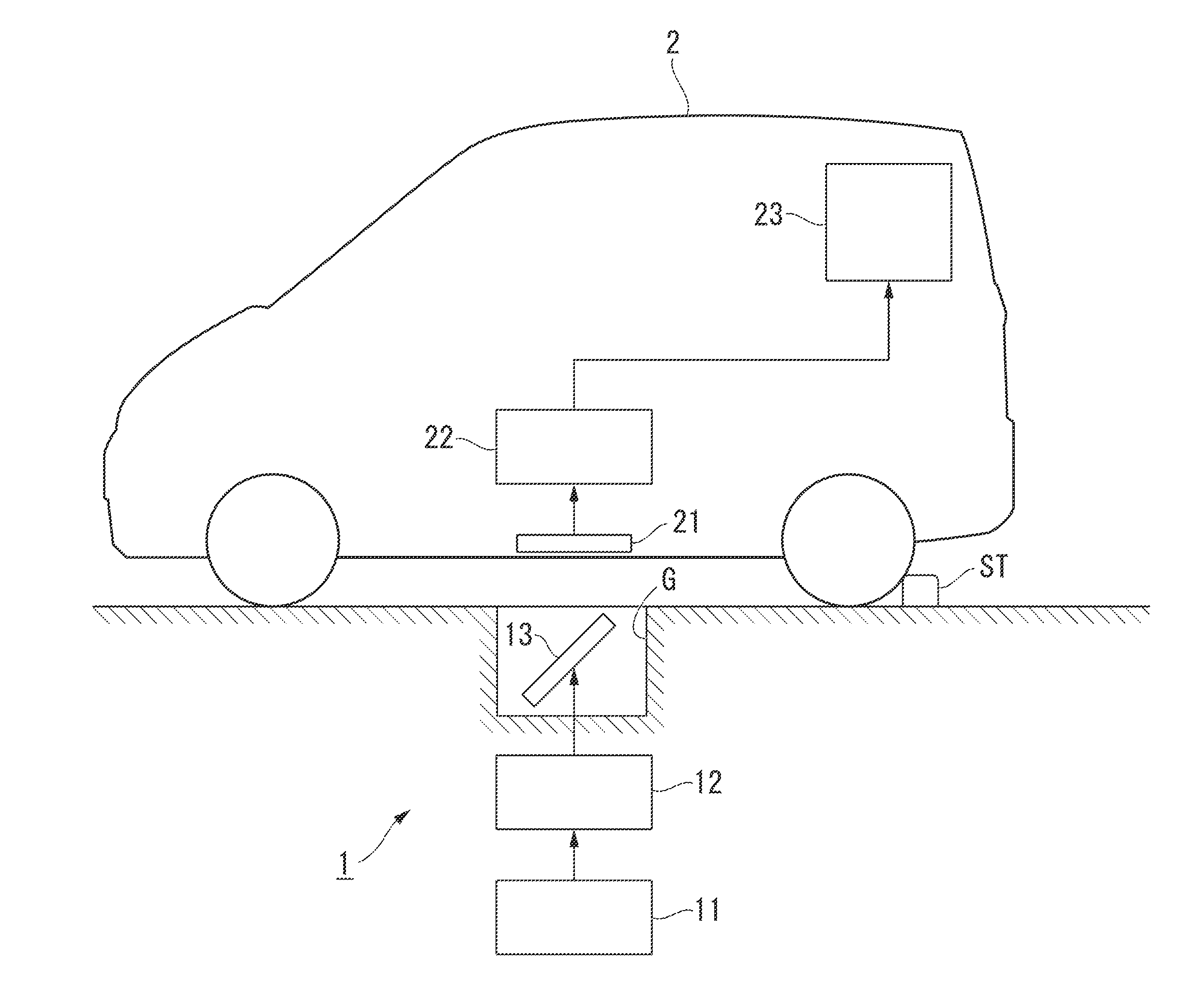
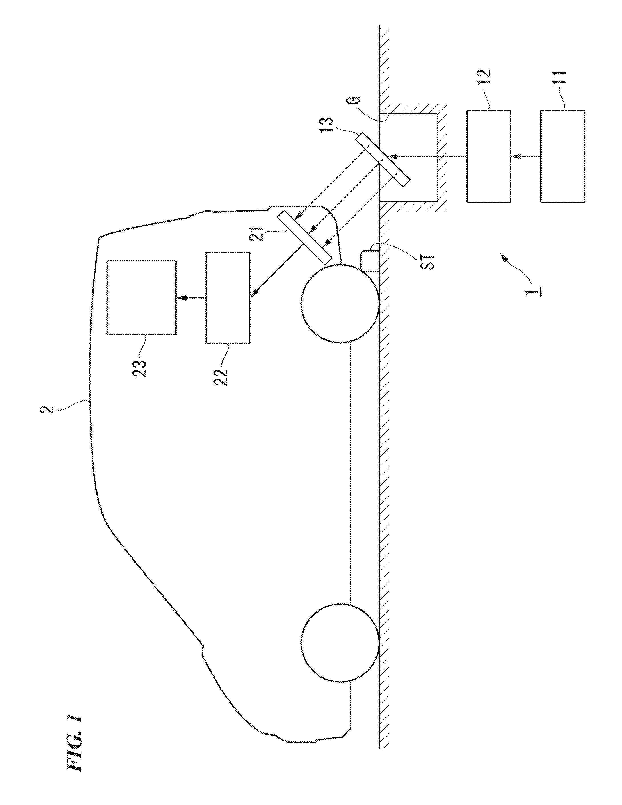
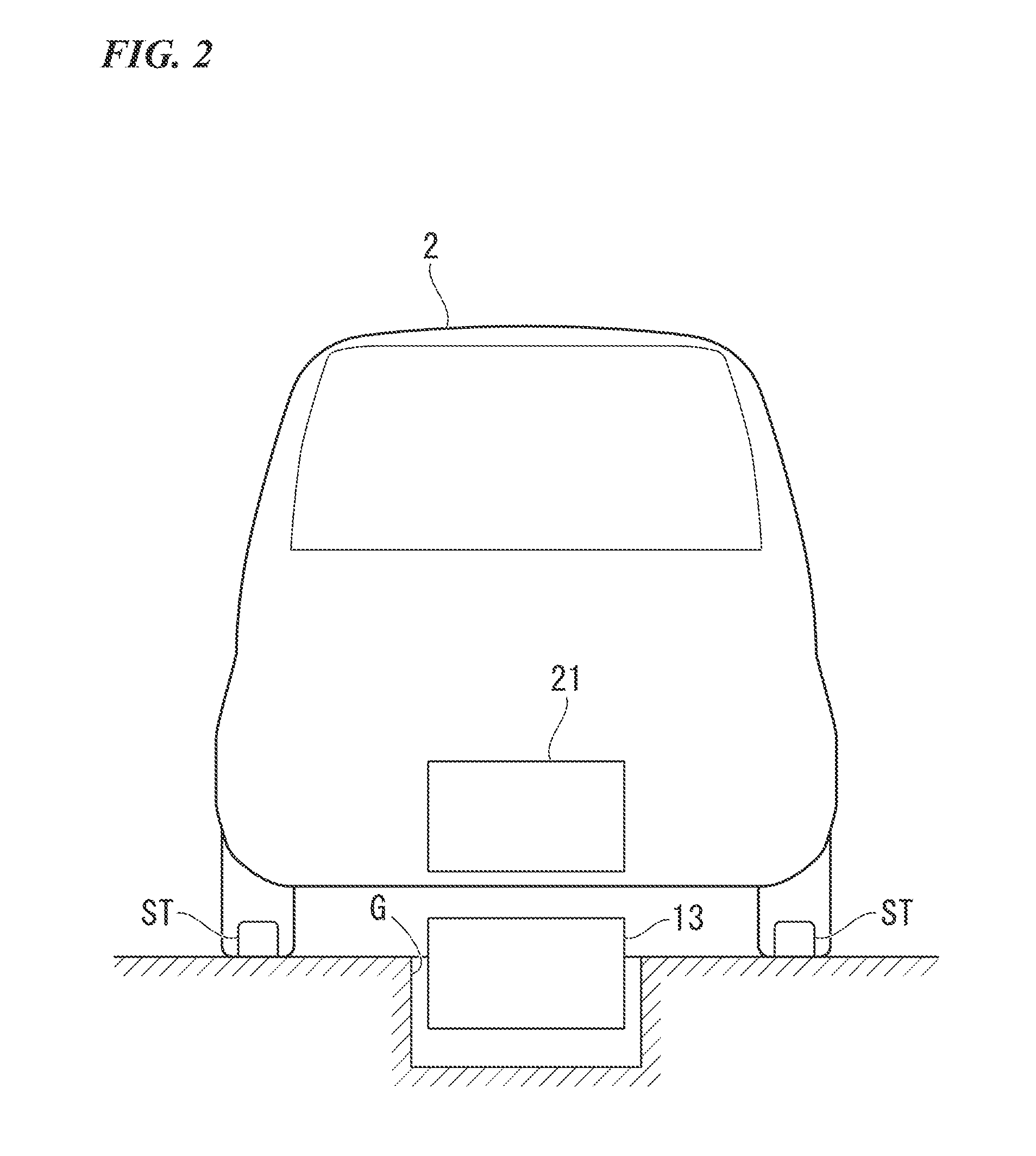
[0026]FIGS. 1 and 2 are diagrams showing main part configurations and a positional relationship of a wireless power transmission device and a vehicle according to the first embodiment of the present disclosure. FIG. 1 is a diagram when the wireless power transmission device and the vehicle are viewed from the side and FIG. 2 is a diagram when the wireless power transmission device and the vehicle are viewed from the back.

[0027]As shown in FIGS. 1 and 2, the wireless power transmission device 1 of this embodiment, for example, is installed in a road surface (installation surface) of a parking place and when an EV 2 serving as the vehicle which travels on the road surface is stopped at a predefined positional relationship (a relative position where an electromagnetic coupling circuit to be described below is formed), it is possible to wirelessly transmit electric power to the EV 2 (power with which a storage battery 23 is charged). The wireless power transmission device 1 includes a p...

second embodiment

[0048]FIG. 4 is a diagram showing main part configurations and a positional relationship of a wireless power transmission device and a vehicle according to the second embodiment of the present disclosure. FIG. 4 is a diagram when the wireless power transmission device and the vehicle are viewed from the side. As shown in FIG. 4, the wireless power transmission device 1 of this embodiment has a position of a power-supplying coil 13 different from that of the first embodiment and an EV 2 of this embodiment has a position of a power-receiving coil 21 different from that of the first embodiment.

[0049]That is, the power-supplying coil 13 provided in the wireless power transmission device 1 is installed in a state in which the entire power-supplying coil 13 has been embedded below the road surface at a stopping position at which the EV 2 should stop. Specifically, the power-supplying coil 13 is installed to be slanted relative to a horizontal plane inside a groove G formed in front of a v...


PUM

PropertyMeasurementUnit
voltageaaaaaaaaaa
poweraaaaaaaaaa
electric poweraaaaaaaaaa

Abstract

A wireless power transmission device includes a power-supplying coil configured to wirelessly transmit power to an electric vehicle (EV) serving as a vehicle, be installed in a slanted state or perpendicularly to a horizontal plane, and form an electromagnetic coupling circuit along with a power-receiving coil provided in the EV.

Description

TECHNICAL FIELD[0001]The present disclosure relates to a wireless power transmission device capable of wirelessly transmit power and a vehicle capable of receiving the power transmitted from the wireless power transmission device.[0002]This application is a continuation application based on a PCT Patent Application No. PCT / JP2013 / 063386 filed on May 14, 2013. The content of the PCT application is incorporated herein by reference.BACKGROUND ART [0003]In recent years, the number of vehicles including an electric motor with an internal combustion engine or instead of the internal combustion engine as a power generation source has increased so as to realize a low carbon society. An electric vehicle (EV) is a representative vehicle including the motor instead of the engine and a hybrid vehicle (HV) is a vehicle including the motor with the engine. Such a vehicle includes a rechargeable storage battery (for example, a secondary battery such as a lithium ion battery or a nickel-metal hydri...

Claims


Application Information

Patent Timeline
Patent Type & Authority Applications(United States)
IPC IPC(8): B60L11/18H01F38/14H02J7/00
CPCB60L11/182H01F38/14H02J7/0042H02J5/00Y02T10/7072Y02T90/14B60L53/124B60L53/126Y02T10/70H02J50/12H02J50/60Y02T90/12
Inventor NIIZUMA, MOTONAO
Owner IHI CORP
Why Eureka
Try Eureka