Power Assist Device and Brake System

a technology of power assist device and brake system, which is applied in the direction of belt/chain/gearing, vehicle components, belt/chain/gearing, etc., can solve the problems of poor power transmission efficiency, still exist high cost or bulky volume, so as to improve the efficiency of power transmission of the booster

Active Publication Date: 2016-09-29
ROBERT BOSCH GMBH
View PDF21 Cites 7 Cited by
  • Summary
  • Abstract
  • Description
  • Claims
  • Application Information

AI Technical Summary

Benefits of technology

[0007]The main technical problem to be solved by the invention is to improve the efficiency in power transmission of a booster.

Problems solved by technology

Due to a limited manual power, a boosting device is often required for the operation of vehicle.
CN1872599A, such problems as poor efficiency in power transmission, loud noise in power transmission, high cost or bulky volume still exist.

Method used


Image

  • Power Assist Device and Brake System
  • Power Assist Device and Brake System
  • Power Assist Device and Brake System

Examples


Embodiment Construction

[0032]The specific embodiments of the invention will be described below in detail with reference to the accompanying drawings in order that those skilled in the art can precisely understand the subject matter claimed in the invention.

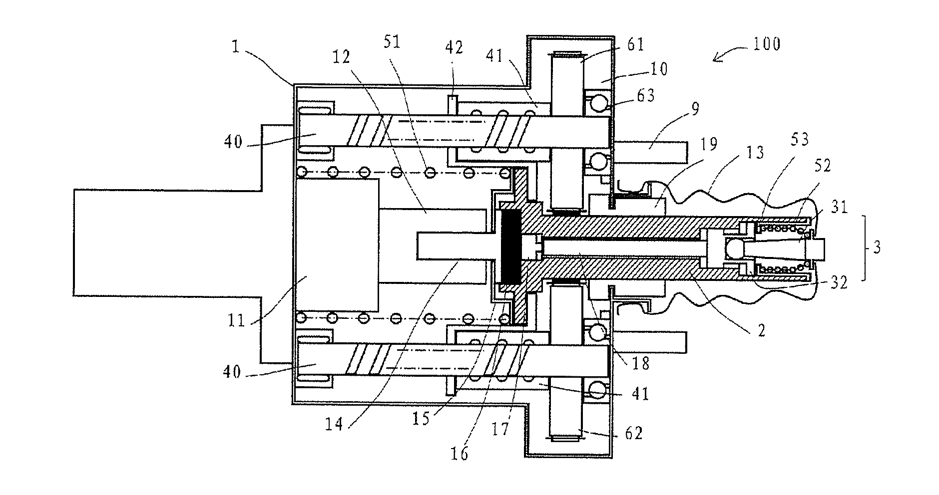
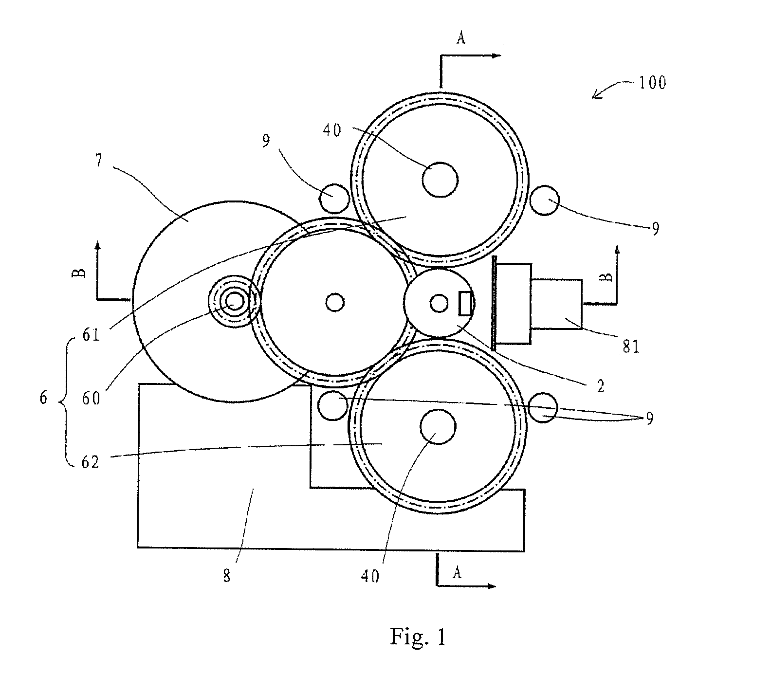
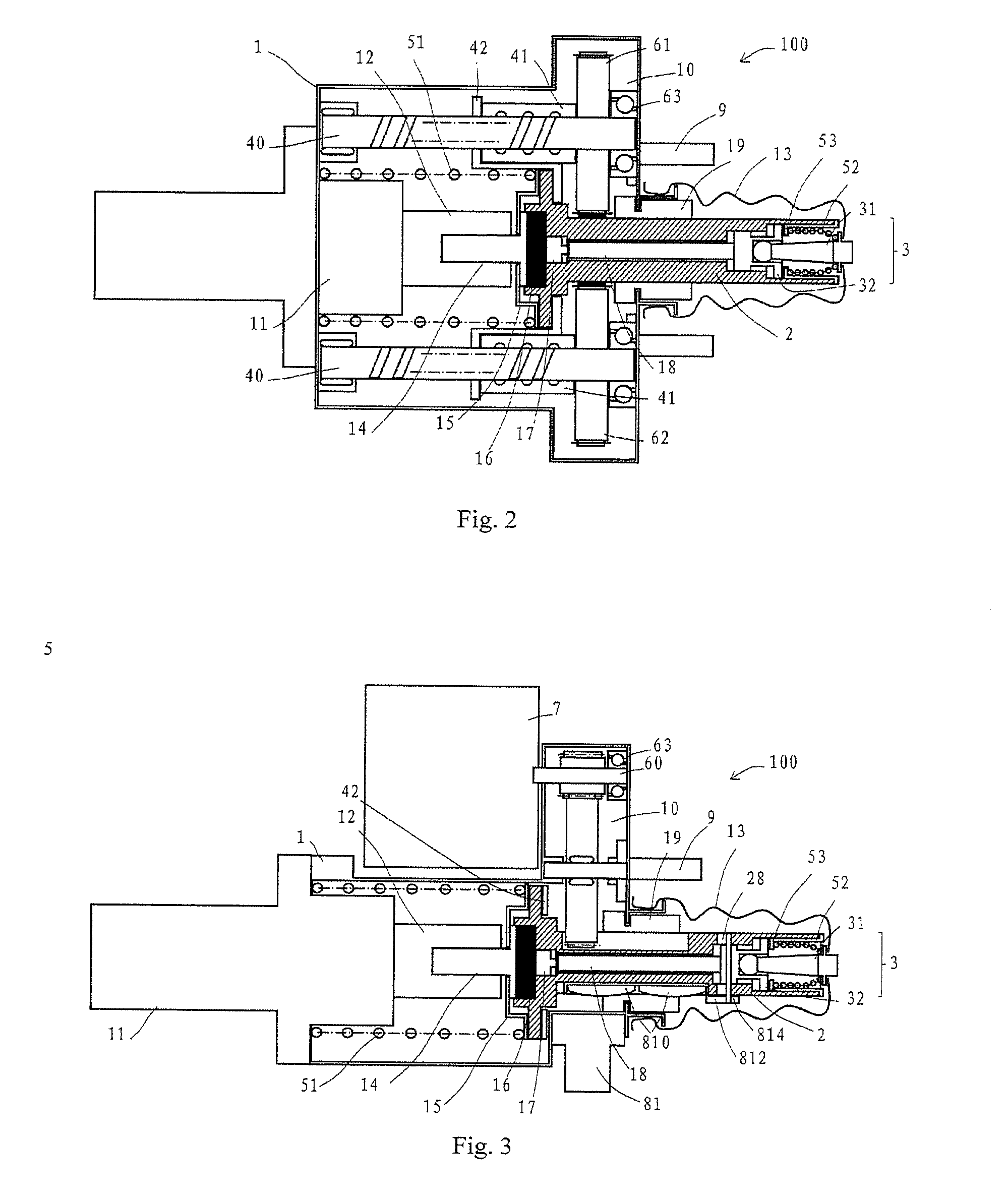
[0033]The invention provides a braking system which comprises a booster 100 and a hydraulic system as shown in FIGS. 1-7, and the hydraulic system comprises a main braking cylinder 11 having a piston 12. Specific embodiments of the booster 100 provided by the invention will be described below in details.

[0034]With reference to FIGS. 1-7, the booster 100 according to a specific embodiment of the invention is fixed by fixing bolts 9. The booster 100 comprises a valve body 2 and a boosting assembly. The valve body 2 is connected to the piston 12 of the main braking cylinder 11, the boosting assembly comprises a ball screw and an input rotating shaft 60, the ball screw comprises a screw rod 40, a nut 41 and a plurality of balls (not shown) cooperated with a...


PUM


Abstract

The present invention discloses a booster (100) and a brake system. The booster includes a valve body (2) and a boosting assembly including a ball screw. The ball screw includes a screw rod (40), a nut (41) and a plurality of balls cooperating with and between the screw rod (40) and the nut (41). The nut (41) is linked with the valve body (2) and the nut (41) moves along a straight line on its cooperated screw rod (40) so as to drive the valve body (2) to move along a straight line. The brake system includes the booster (100) and a hydraulic system. The hydraulic system includes a braking main cylinder (11) having a piston (12), and the valve body (2) is connected to the piston (12). The booster can provide high transmission efficiency.

Description

FIELD OF THE INVENTION[0001]The invention relates to a device for providing boosting force, and in particular, to a booster and a brake system.BACKGROUND[0002]Due to a limited manual power, a boosting device is often required for the operation of vehicle. For example, boosters such as compressed air, high pressure oil are used to operate associated devices in a vehicle so as to achieve the purpose of convenient use. The development of modern automotive brakes originates from primitive mechanical control devices. The most primitive braking control is only that the driver operates a set of simple mechanical devices to exert an acting force to the brake. In those days, the vehicle has a light weight and a low speed, and thus a mechanical braking can already meet the requirements of automotive braking. However, with the increase of the weight of vehicle itself, a boosting device becomes more and more important for a brake.[0003]Chinese invention patent application No. CN102205838A which...

Claims


Application Information

Patent Timeline
Patent Type & Authority Applications(United States)
IPC IPC(8): B60T13/74
CPCB60T13/745B60T13/02F16H25/2204
Inventor ZHANG, QIUSHENG
Owner ROBERT BOSCH GMBH
Why Eureka
Try Eureka