
Charging connector having a housing having a cover and a base with positioning projections

a charging connector and projection technology, applied in the direction of charging stations, coupling device connections, transportation and packaging, etc., can solve the problems of two half members not being positioned and the base cannot be s

Inactive Publication Date: 2014-03-25
SUMITOMO WIRING SYST LTD
View PDF14 Cites 13 Cited by
  • Summary
  • Abstract
  • Description
  • Claims
  • Application Information

AI Technical Summary

Benefits of technology

The technical effects of this patent include the ability to position half members without being restricted to specific locations and minimize rotational force when a bolt is tightened. The grip has no firmly held member, which allows for displacement of the half members, but the positioning portion prevents this.

Problems solved by technology

Accordingly, the pin fitting hole can be provided if sufficient space exist in a housing, but the base cannot be set and the two half members cannot be positioned if insufficient space exists in the housing.

Method used


Image

  • Charging connector having a housing having a cover and a base with positioning projections
  • Charging connector having a housing having a cover and a base with positioning projections
  • Charging connector having a housing having a cover and a base with positioning projections

Examples


Embodiment Construction

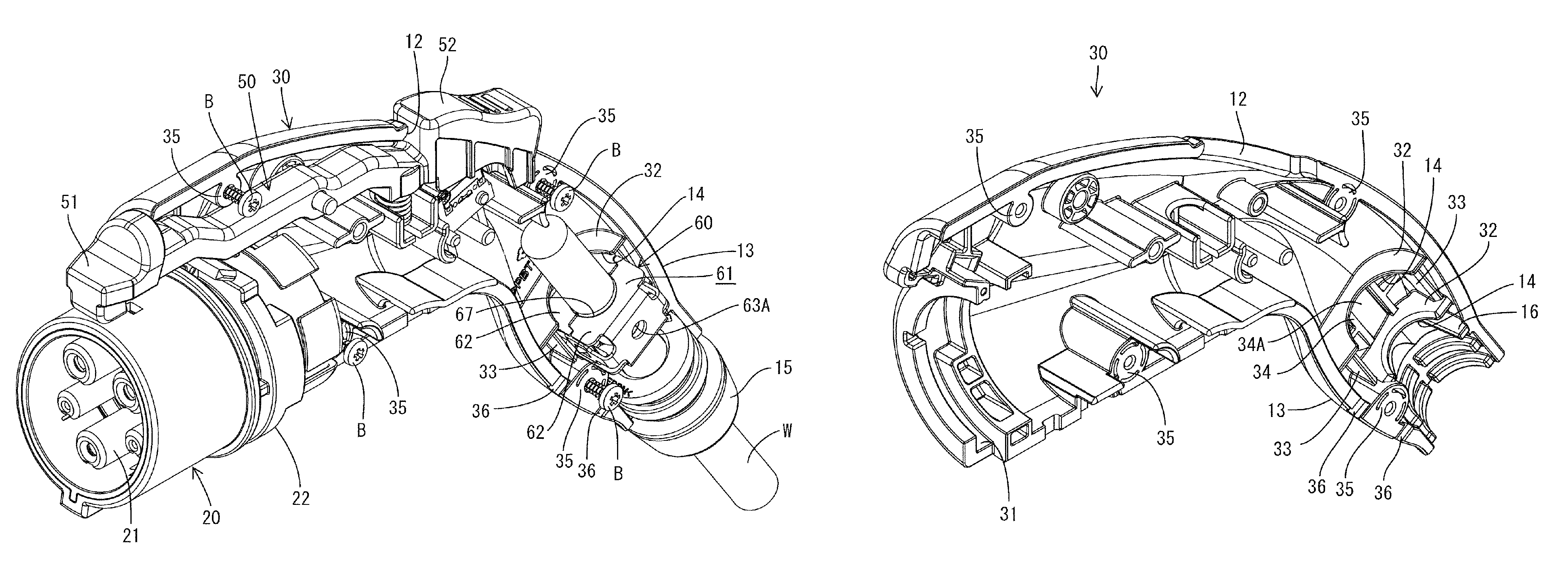
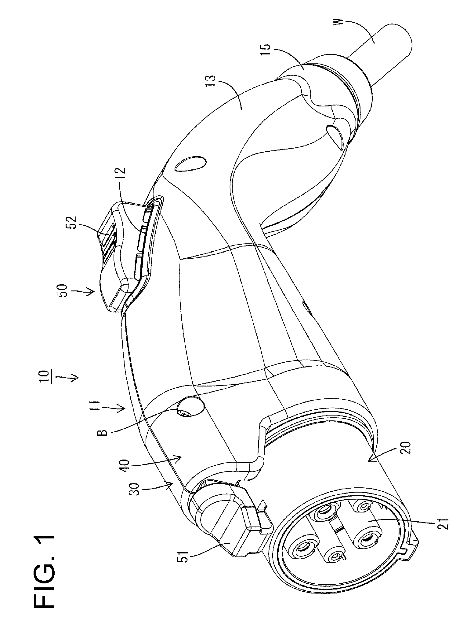
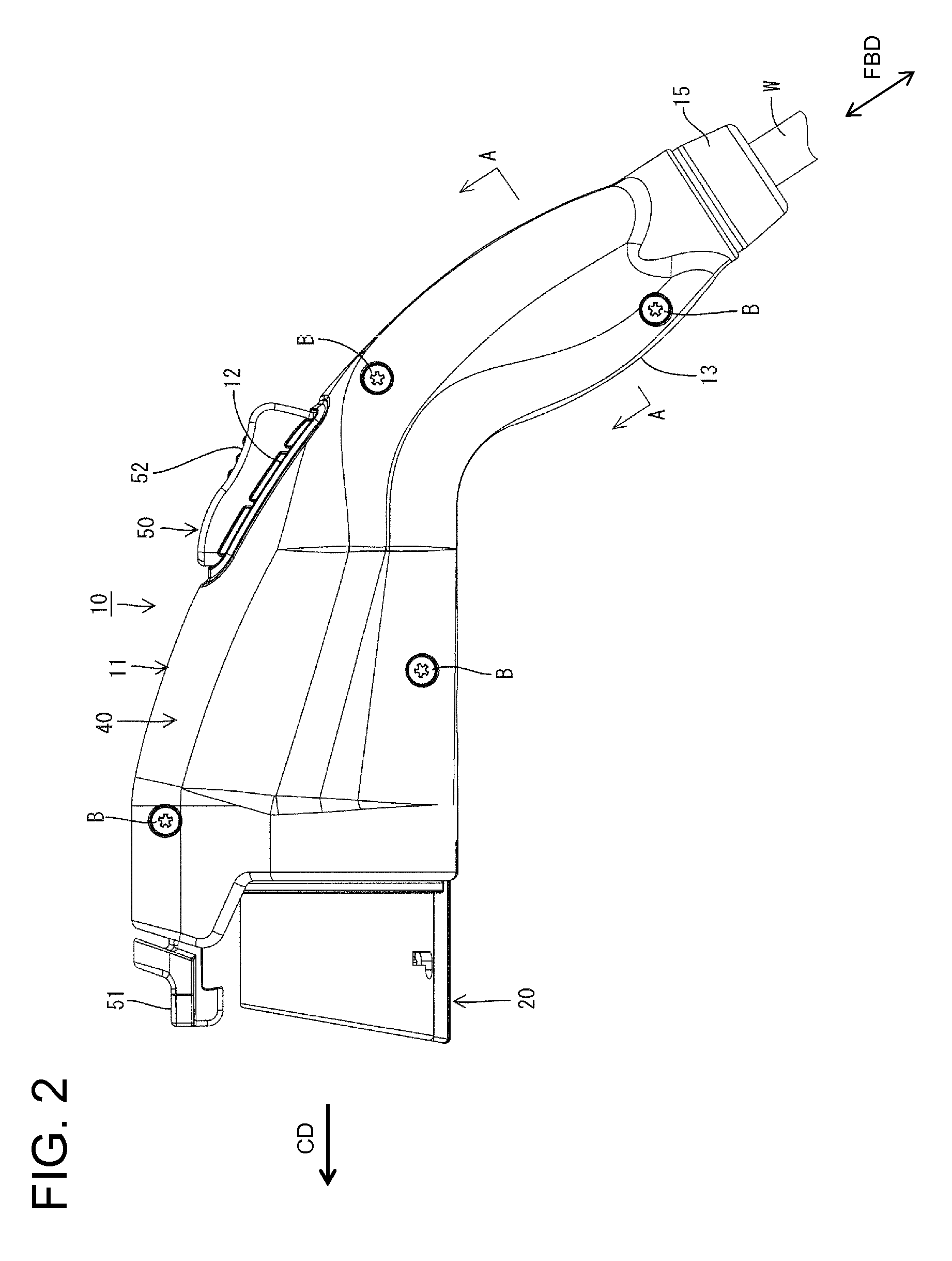
[0031]A charging connector in accordance with the invention is identified generally by the number 10 and includes a housing 11 having a pistol shape. The housing 11 comprises a front housing 20 connectable to a vehicle-side connector (not shown). A base housing 30 and a cover housing 40 hold the front housing 20 from left and right sides. Further, as shown in FIG. 2, the base housing 30 and the cover housing 40 are fixed to one another by bolts B. It should be understood that the base housing 30 and the cover housing 40 may be fixed to one another by clips, retainers, latches, or similar coupling members.

[0032]As shown in FIG. 3, at least one wire W is held in a clip 60 housed in a grip 13 of the housing 11. The clip 60 preferably is made of metal The grip 13 extends rearward from a release button 52 and is aligned obliquely down with respect to a connecting direction CD of the front housing 20 to the vehicle-side connector. Note that a longitudinal direction of the wire W is referr...


PUM


Abstract

A charging connector (10) has a housing (11) integrally formed by bolting a pair of half members. A front housing (20) is mounted in a front end portion of the housing (11) and tightly held by two housings (30, 40). A positioning rib (16) for positioning the housings (30, 40) is provided at a position of the base-side housing (30) distant from the front housing (20) and comes into contact with the inner surface of the cover-side housing (40) when the housings (30, 40) are assembled properly.

Description

BACKGROUND OF THE INVENTION[0001]1. Field of the Invention[0002]The invention relates to a charging connector.[0003]2. Description of the Related Art[0004]Japanese Unexamined Patent Publication No. 2003-36924 discloses a charging connector for charging a battery installed in an electric vehicle. The charging connector includes a grip integrally formed by bolting first and second half members together. A fitting pin projects from a surface of the first half member and is fit in a pin fitting hole of the second half member to position the half members.[0005]However, a base is required where the pin fitting hole is formed, and such a base normally is provided by padding on the facing surface of the other half member projecting radially inwardly. Accordingly, the pin fitting hole can be provided if sufficient space exist in a housing, but the base cannot be set and the two half members cannot be positioned if insufficient space exists in the housing.[0006]The invention was completed in ...

Claims


Application Information

Patent Timeline
Patent Type & Authority Patents(United States)
IPC IPC(8): H01R13/627
CPCY02T90/14B60L2270/34H01R13/502Y02T90/121H01R2201/26H01R13/5825B60L2270/32Y02T10/7088Y02T10/7005B60L11/1818B60L53/16H01R13/512H01R13/516H01R43/20Y02T10/70Y02T10/7072
Inventor OSAWA, KIYOSHI
Owner SUMITOMO WIRING SYST LTD
Learn More