
Golf putter

Inactive Publication Date: 2009-03-12
SCHMIDT JACOB H
View PDF7 Cites 0 Cited by
  • Summary
  • Abstract
  • Description
  • Claims
  • Application Information

AI Technical Summary

Benefits of technology

[0020]Weight of the club head at the heel and toe ends can also be varied to maximize reduction of torque communication to the shaft during the moment of impact with a golf ball.
[0029]It is a further object of this invention to provide a putter with a center attached hosel that will eliminate or reduce the amount of initial skidding or back spinning of the golf ball after leaving the face of the putter at impact through smoother contact, to thereby provide a smoother transition of the golf ball from its stationary position to its final free roll.

Problems solved by technology

The putting portion of the game can be especially vexing to golfers since the ball must be accurately driven on the green, taking into consideration the slant of the green and many other variables.
However, most putters of either design have an engagement of the shaft of the club to the hosel engaging the head in a position and attachment mode at the heel end which causes unwanted torque or twisting of the head at the moment of impact with the ball.
Additionally, many such shaft and hosel engagements marginalize the feel or tactile sensation of the strike on the ball communicated to the hands of the user gripping the shaft.
However, in such an engagement, the shaft can block the view of the ball since it runs through the center of the club.
In center mounted heads struck off center, or heel mounted heads even struck on center, the torque generated and resulting twisting tend to rotate the engaged shaft and can easily misdirect the ball along the wrong trajectory from that intended.

Method used


Image

  • Golf putter
  • Golf putter
  • Golf putter

Examples


Embodiment Construction

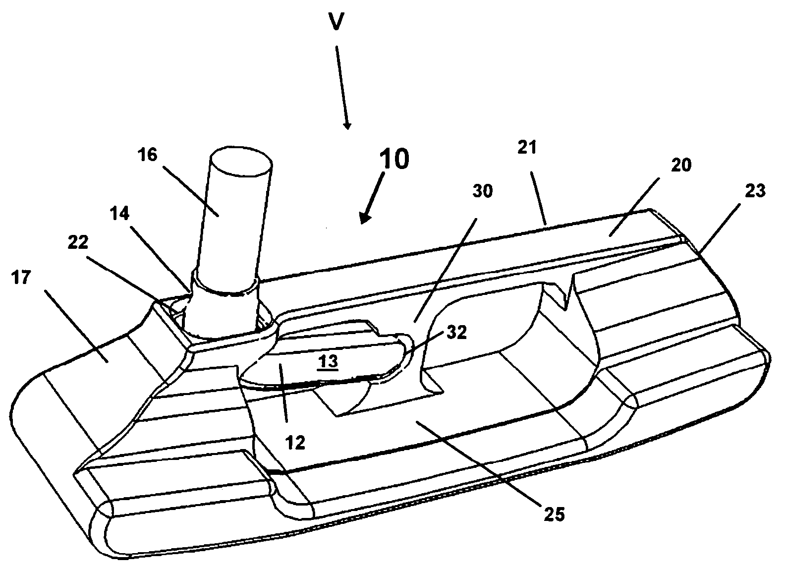
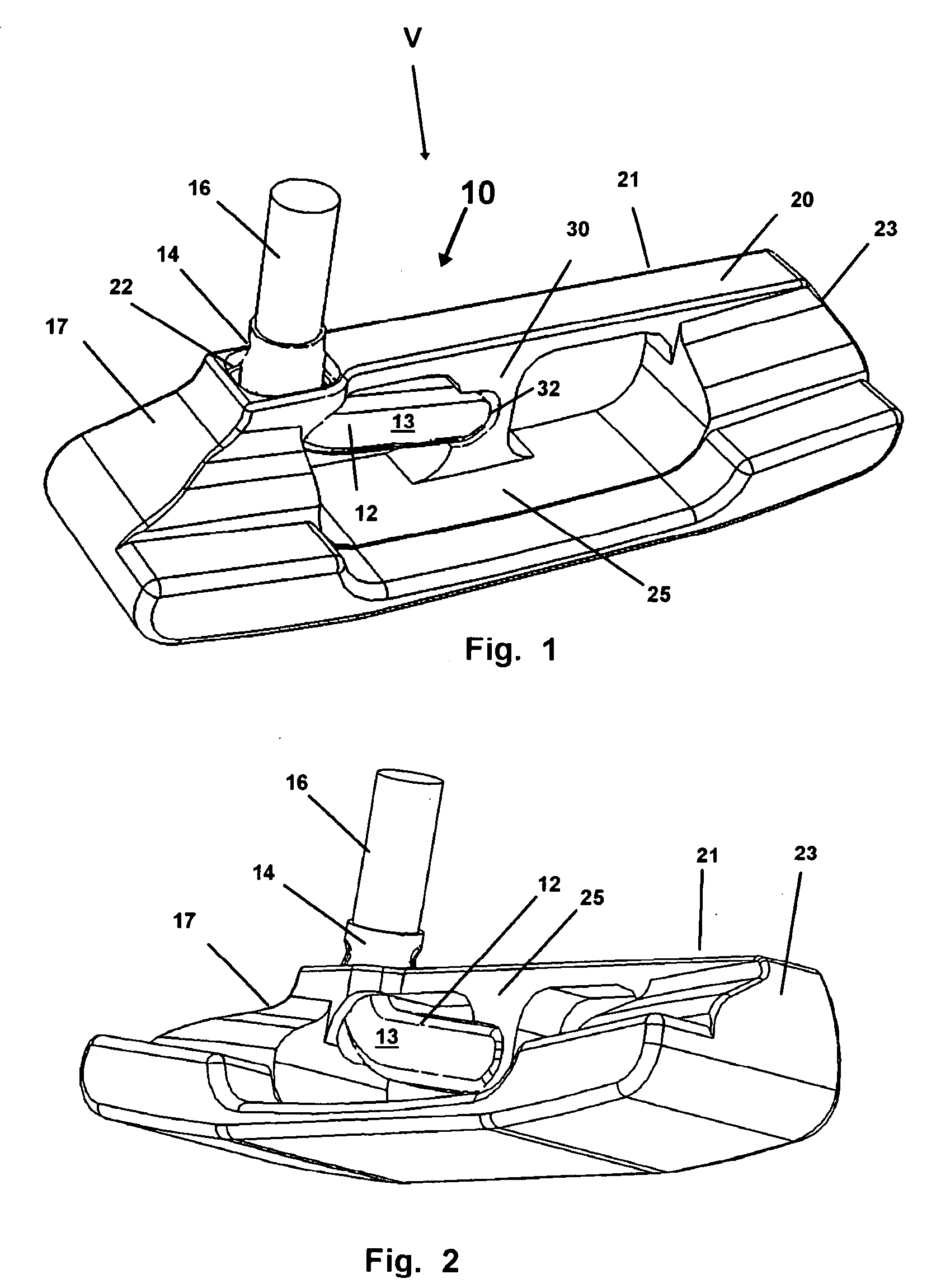
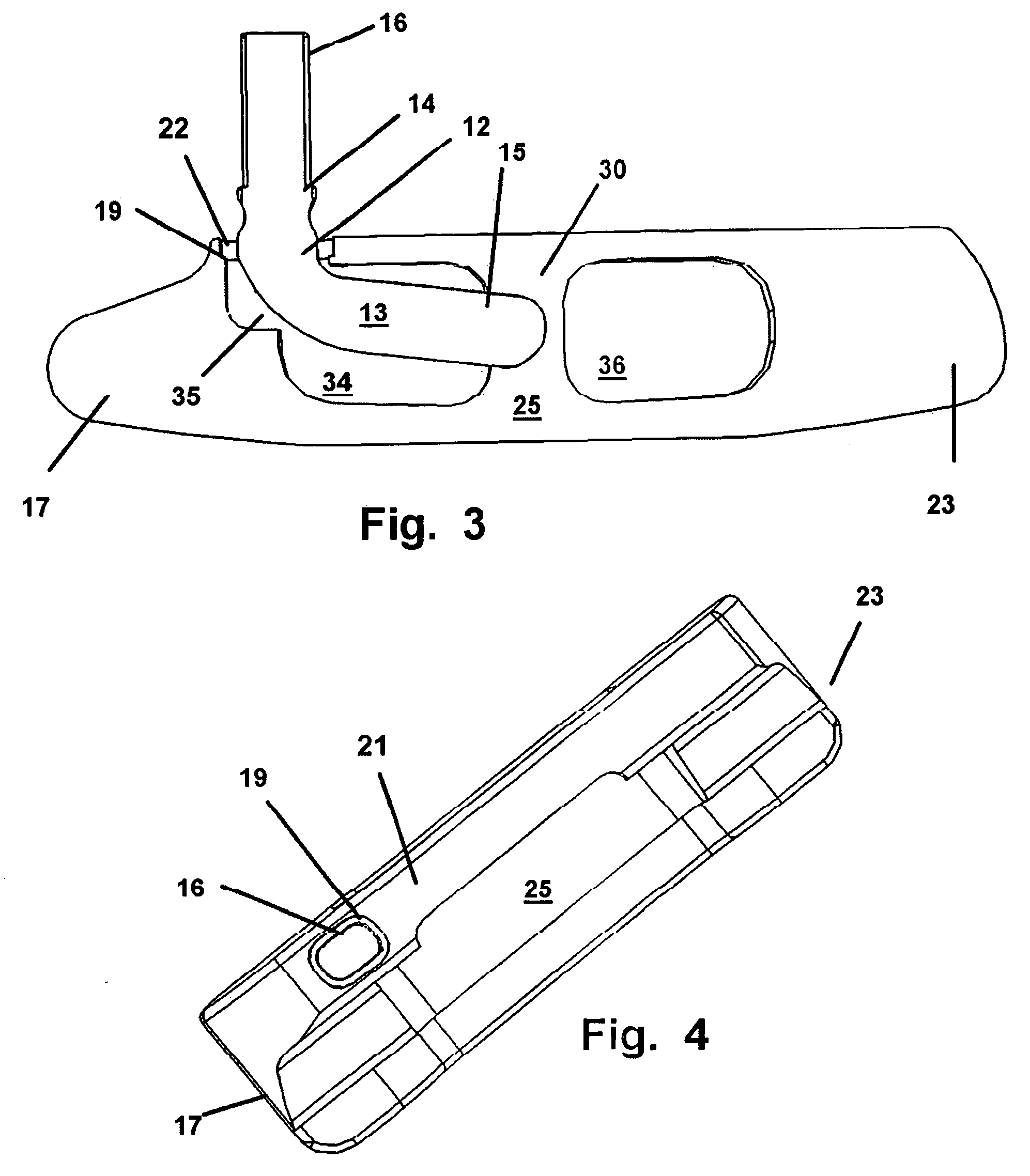
[0042]Referring now to all of the drawings in FIGS. 1-11, wherein similar parts are identified by like reference numerals, the device 10 is depicted in FIG. 1 which shows a perspective view. As can be seen in FIGS. 1-3 in a mode of the device 10 employing a hosel 12 to shaft 16 engagement of the head 21, the hosel 12 has a collar 14 at a first end which is adapted to be engaged on a golf club shaft 16 in which the club is gripped by a user. Or, alternatively as shown in FIG. 3, the hosel 12 may have an outside diameter at its first end adapted for insertion inside the axial passage at the distal end of the shaft 16.

[0043]As shown in FIGS. 1-23, and 5, the hosel 12 has member 13 communicating from the first end, to a distal end 15 which has a circumference sized smaller than the passageway communicating through the heel 17 end of the head 21 to the center portion where the distal end 15 connects with the head 21.

[0044]The passage in one favored mode is provided by an aperture 18 form...


PUM


Abstract

A golf putter providing a center mount of the hosel to the club head and a shaft engagement to the hosel at the heel end of the club head. The center mount provides the sole engagement of the hosel to the head as a gap is formed by a pathway formed through the body of the head which is larger than the circumference of the hosel in its communication therethrough. The centered engagement provides better touch to the user and feedback on striking a ball while concurrently removing the shaft from the user's line of sight to the ball and club face and reduces the twist or torque at impact with a golf ball, thereby increasing the moment of inertia.

Description

[0001]This application claims the benefit of U.S. Provisional Application 60 / 970,962 filed Sep. 9, 2007, and which is entirely incorporated herein by reference.FIELD OF THE INVENTION[0002]The disclosed system and method relate to golf clubs. More particularly it relates to a putter style golf club, having novel central attachment of the distal end of the hosel or club shaft, which engages the head of the putter, solely at a central portion of the club.BACKGROUND OF THE INVENTION[0003]In the sport of golf, golf clubs are employed to hit a golf ball around the various portions of the course. As a general rule golf clubs fall into three broad categories including woods, irons, and the putter. Woods have club heads formed of wood and / or metal and are designed for striking and propelling the ball long distances down the fairway portion of the golf course. Irons are the clubs employed by golfers for medium distance driving of the ball.[0004]In a conventional set of clubs including such wo...

Claims


Application Information

Patent Timeline
IPC IPC(8): A63B53/00
CPCA63B53/02A63B60/50
Inventor SCHMIDT, JACOB H.
Owner SCHMIDT JACOB H
Learn More