
Curvature for pathway of a locating device or chuck

a technology of locating device and chuck, which is applied in the direction of chucks, mechanical devices, manufacturing tools, etc., can solve the problems of workpiece chatter, binding or mechanical interference, and the type of chuck becomes bulky, and achieves greater range of movement, less rotational force, and rigidity of workpieces

Active Publication Date: 2020-05-19
FRANTZ WALTER FORREST
View PDF20 Cites 0 Cited by
  • Summary
  • Abstract
  • Description
  • Claims
  • Application Information

AI Technical Summary

Benefits of technology

The patent describes a new way to make curved shapes that can be used to hold workpieces rigidly during machining processes. These shapes are made by using a special spiral-part that keeps the workpiece in the correct position, minimizing movement and reducing interference between parts. This results in improved quality, safety, and speed of processing. Compared to previous methods, this new technique produces stronger push / pull forces, reduces friction, noise, and mechanical interference, and allows for more efficient use of locking force. Overall, this patent provides a better way to hold workpieces and to improve machining processes.

Problems solved by technology

But when attempting to chuck (center and clamp) a workpiece that is large or very small, those types of chucks become bulky, heavy, or not feasible because of the micro-scale.
The key issue with the Longworth Chuck is that it is based on a constant curvature arc—a segment of a circle.
This limits the size of objects that can be centered on a fixed size chuck and does not provide for a near constant perpendicular force resulting in workpiece chatter, or causing binding or mechanical interference if each slot is too long relative to the size of the chuck.
But when the pushing slot becomes less perpendicular more force is required to move the clamp and the mechanism can jam or decreases the holding-force when locked.
Also, because perpendicularity is not present where the two slots intersect (except at possibly one point) and the intersect angle increases as it moves inward, the slot clamp-up force varies causing workpiece chatter.
This limits its application, reliability, and use.
The problem is large enough that some machinists avoid use of the Longworth chuck and turn to other more complicated and less versatile chuck methods.

Method used


Image

  • Curvature for pathway of a locating device or chuck
  • Curvature for pathway of a locating device or chuck
  • Curvature for pathway of a locating device or chuck

Examples


Embodiment Construction

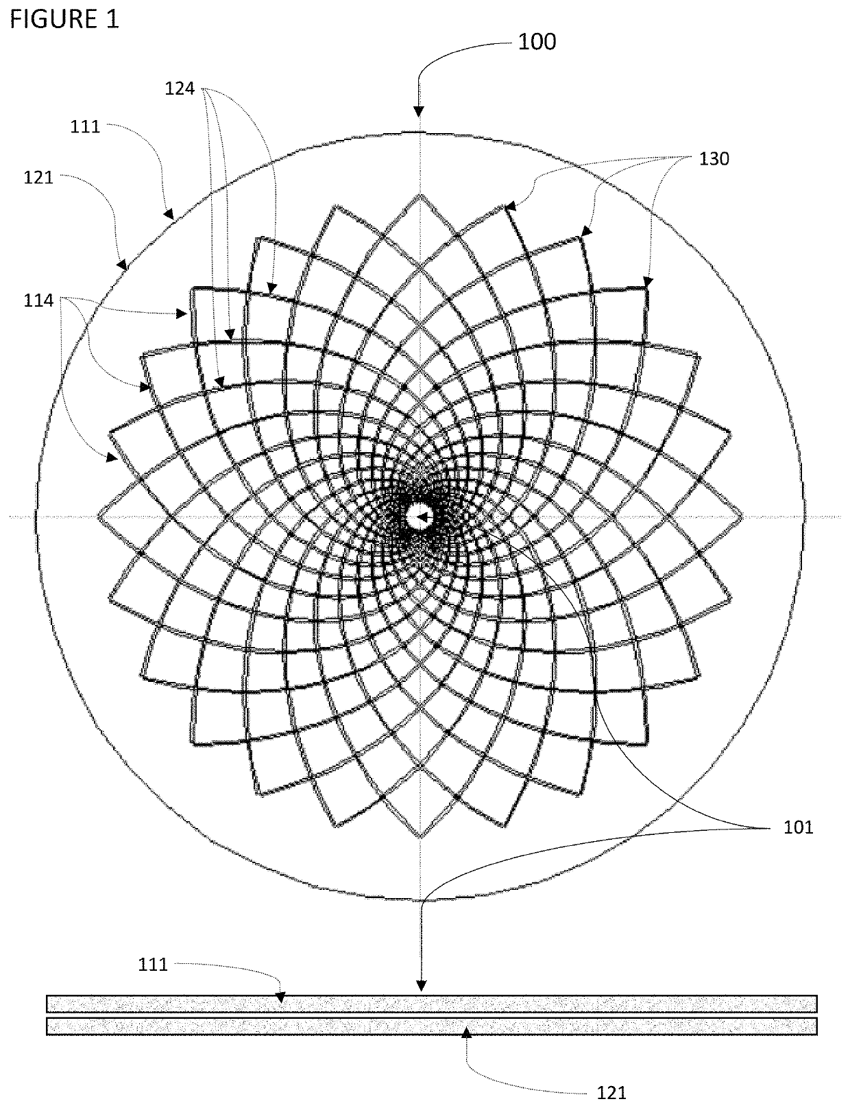
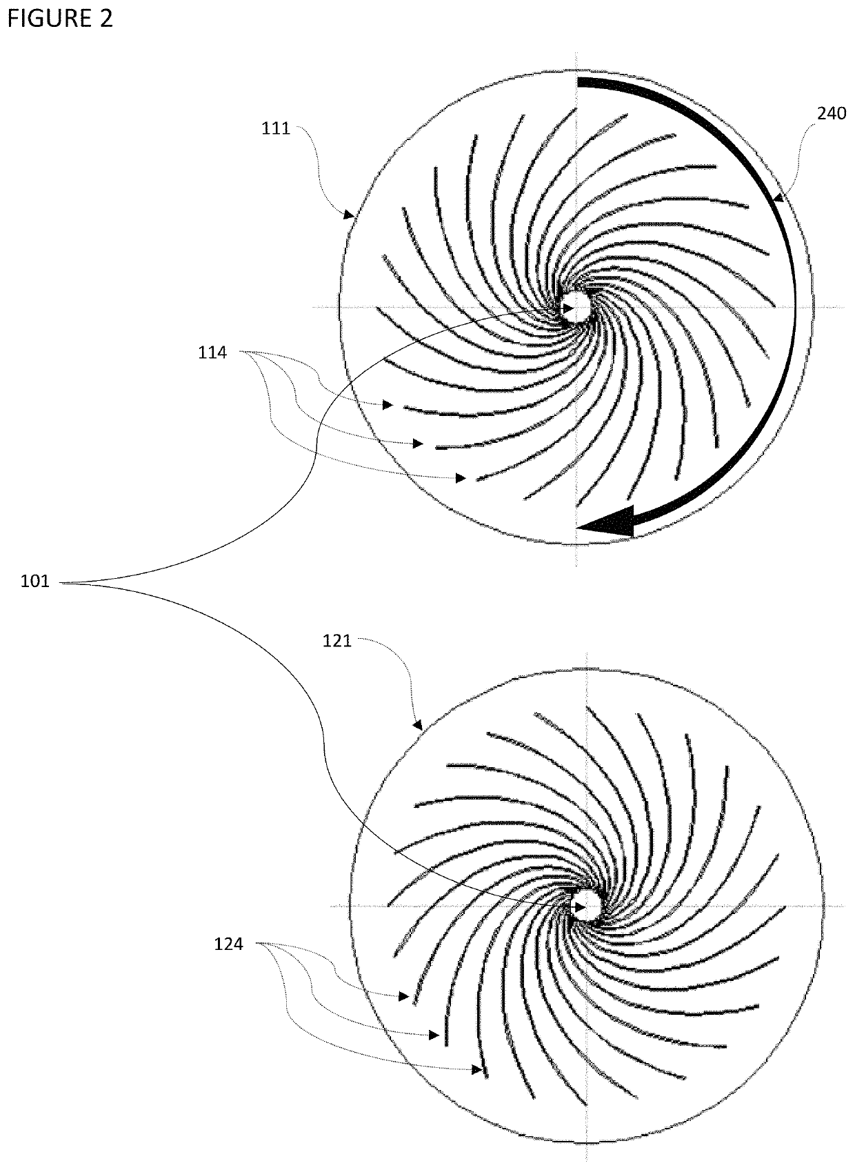
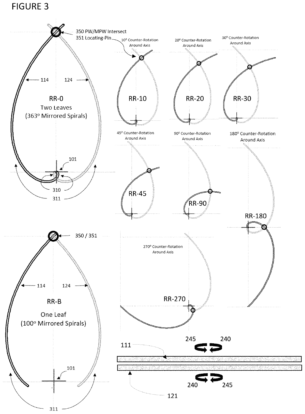
[0022]The focus of this apparatus is on the inventive step—the curvature of the Pathway. The focus is not on the:[0023]Locating-Pin (hard or soft pin, jaw, block, teeth, clamp, spacer, threaded element, motorized device, magnet, electromagnet, plasma, force-field, or other devices used to move, locate, and / or hold a Workpiece,[0024]Rotation-Bushing (pin, bearing, bushing, sleeve, threaded element, motor, axle, gear, spindle, interior or exterior wheels / pins, magnet, electromagnet, plasma, force-field or other devices used to align and / or rotate the rotating surface to the other surface that contain the PW or MPW),[0025]Optional Lock (lock, pin, threaded element, motor, magnet, electromagnet, plasma, force-field, or other devices used to hold the Workpiece),[0026]other features that allows an apparatus to perform in a specific application.

[0027]The design and incorporation of the Locating-Pin, Rotation-Busing, Optional Lock, and other features are up to a person versed in the art and...


PUM


Abstract

Disclosed is the shape of a curvature of two or more pathways for a device having moving parts that cause movement of an object along those pathways, such that the device can locate or hold the object. In the embodiment, an apparatus is described that centers and optionally locks an object at a desired location. The applications for such a device are varied and can range from chucking a workpiece of varying diameters in a lathe, to centering a drone on a landing zone, to medical and scientific devices to capture and center objects to study, to moving atomic level objects using an electromagnetic field. The scope of this disclosure is the mathematics that defines the mirrored curvatures of each curved pathway and the positioning of the curvatures relative to each other, and the relative movement of the mirrored curvatures to cause the desired effect.

Description

BACKGROUND OF THE INVENTION[0001]The market for simple centering mechanisms is large. The most common is a screw-driven type device such as found on a drill to center and clamp a drill bit. Another is on a lathe to chuck small parts. But when attempting to chuck (center and clamp) a workpiece that is large or very small, those types of chucks become bulky, heavy, or not feasible because of the micro-scale. A simple solution that is light weight, easy to handle, scalable to any size, and easy to build (even for holding a large workpiece) for lathe work is called a Longworth Chuck. Its concept is also currently used in the Medical and Aerospace fields. The key issue with the Longworth Chuck is that it is based on a constant curvature arc—a segment of a circle. This limits the size of objects that can be centered on a fixed size chuck and does not provide for a near constant perpendicular force resulting in workpiece chatter, or causing binding or mechanical interference if each slot i...

Claims


Application Information

Patent Timeline
Patent Type & Authority Patents(United States)
IPC IPC(8): B23B31/163B23B31/16
CPCB23B31/16004B23B2231/32Y10T279/1926B23B2231/46B23B31/1627B23B2260/0725
Inventor FRANTZ, WALTER FORREST
Owner FRANTZ WALTER FORREST
Learn More