Method and apparatus to improve performance of power plant steam surface condensers

a technology of steam power plant and surface condenser, which is applied in the direction of machines/engines, lightening and heating apparatus, other domestic objects, etc., can solve the problems of inability to meet the needs of condensate rain, etc., to reduce the susceptibility of condensate rain and reduce the undesirable effects of thermodynamic and condenser performance effects

Active Publication Date: 2014-04-08
BURNS JOHN M +3
View PDF1 Cites 0 Cited by
  • Summary
  • Abstract
  • Description
  • Claims
  • Application Information

AI Technical Summary

Benefits of technology

[0012]In another aspect of the invention, condensate rain flow from lower tube bundles is restrained from a tendency to flow toward a transverse centerline of condenser tube bundles, a condition where condensate temperature falls below steam saturation temperature (i.e., condensate subcooling) and further where condensate is susceptible to absorbing gas. Absorbed gas in condensate especially dissolved oxygen has a corrosive effect on upstream equipment and piping. Restraint and diversion of condensate in this aspect of the invention also promotes reheating as condensate falls toward the hotwell.
[0015]An object of the invention is to diminish undesirable thermodynamic and condenser performance effects attributable to free falling condensate rain within a surface steam condenser.
[0017]Another object of the invention is to diminish undesirable thermodynamic and condenser performance effects of condensate rain from lower tube bundles.
[0018]Another object of the invention is to reduce susceptibility of condensate rain falling from lower tube bundle to absorbing non-condensable gases especially dissolved oxygen.
[0019]Another object of the invention is to protect flow stream of non-condensable gases in space between air cooler section exit and entrance to off-take piping.

Problems solved by technology

However, with requirements for larger and larger plants though the late 1960s to the 1980s and with the advent of nuclear plants and their higher quantities of steam and large size, condensers also grew, usually by an untested, rapid, simple size extrapolation.
Some condenser designs worked well; some did not perform as well, particularly after design extrapolations to much larger sizes.
Utilities as a rule did not have personnel possessing a sufficient detailed condenser design background in this equipment to take an effective action.

Method used


Image

  • Method and apparatus to improve performance of power plant steam surface condensers
  • Method and apparatus to improve performance of power plant steam surface condensers
  • Method and apparatus to improve performance of power plant steam surface condensers

Examples


Embodiment Construction

[0027]1. Intermediate Baffles Between Bundles

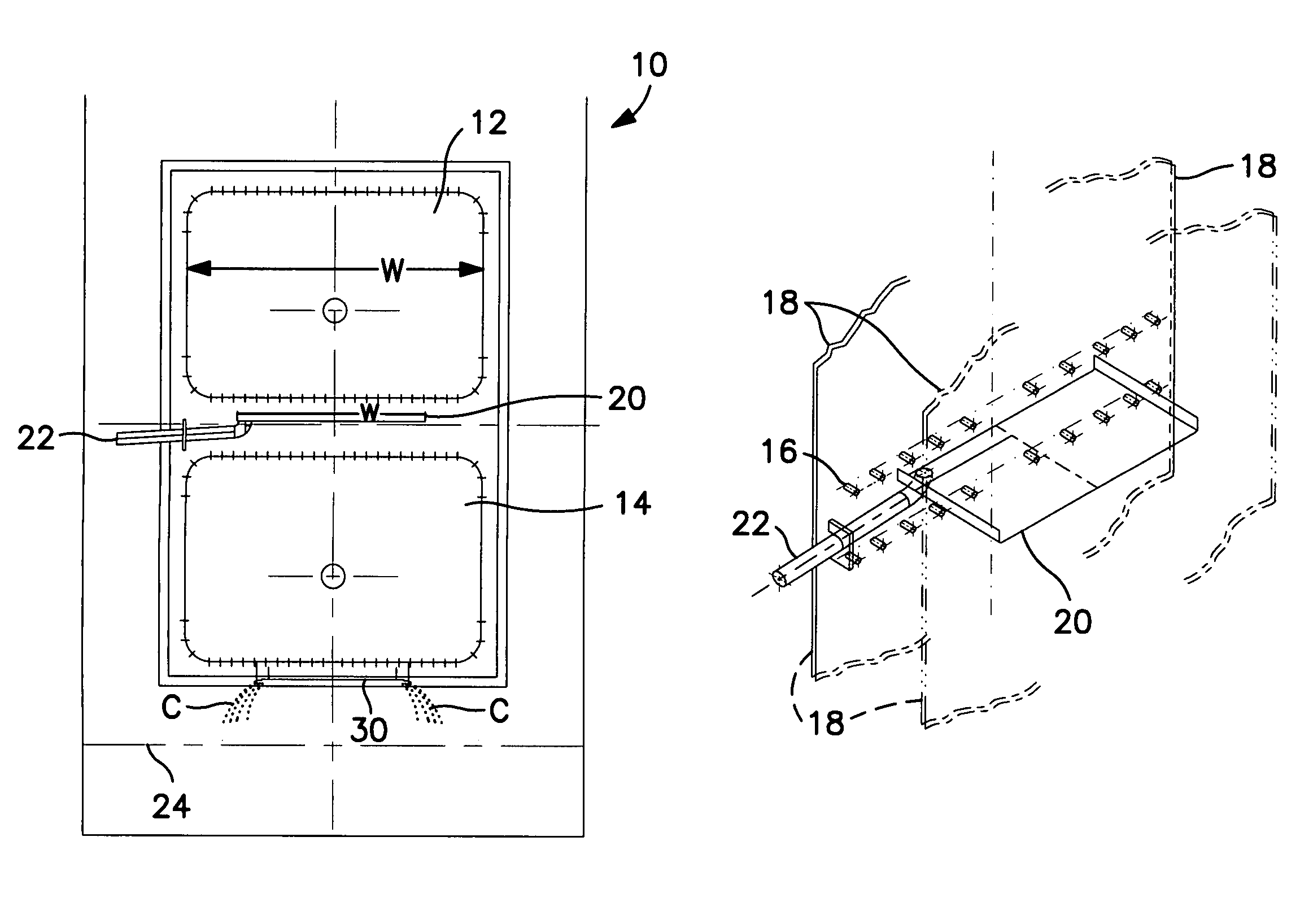
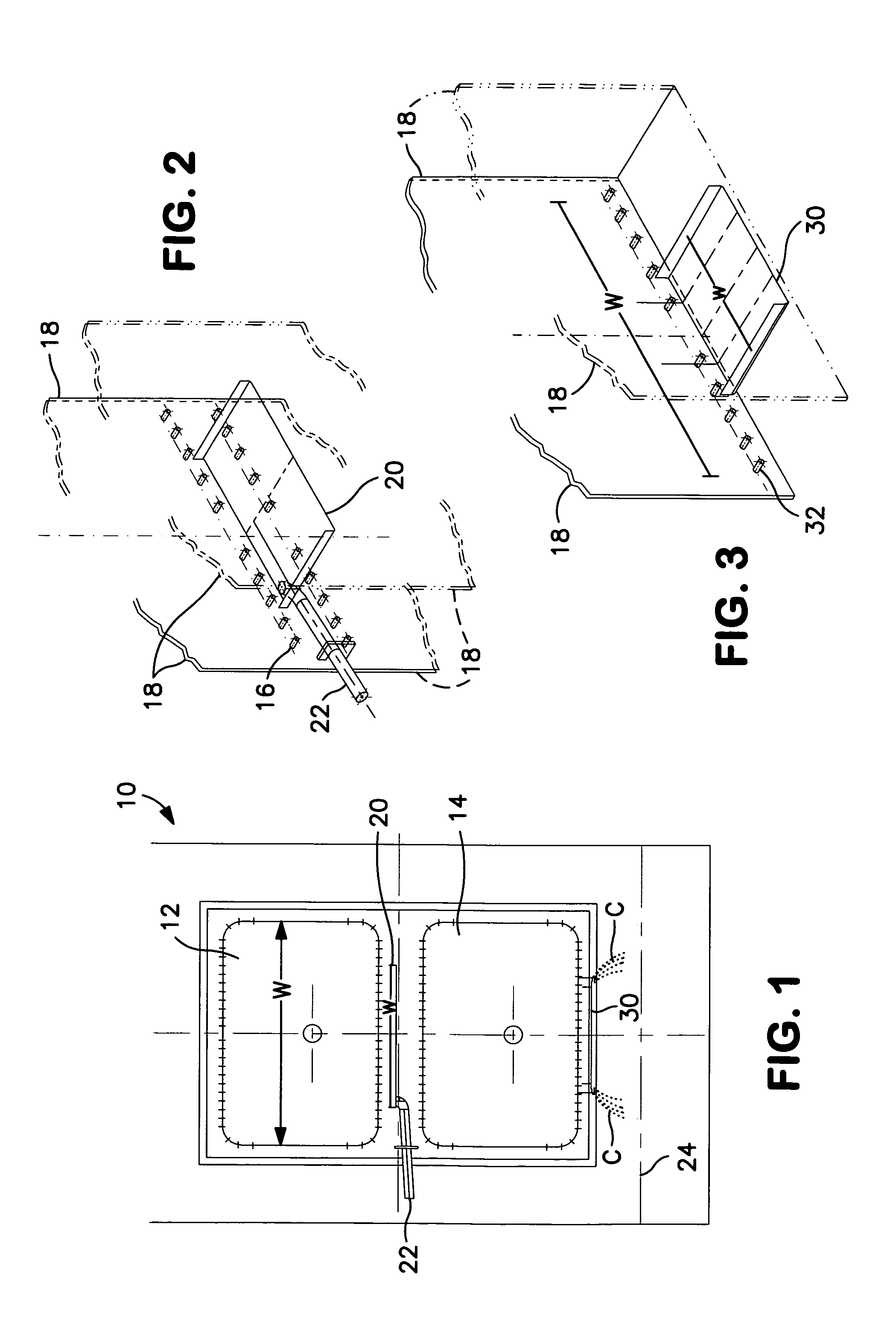
[0028]Referring to FIGS. 1-3 of the drawing, it is to be understood that when the design of condenser 10 is such that two or more large tube bundles 12, 14 are arrayed vertically, the water loading of the steam condensed (condensate) in the upper bundle falls through the lower bundle. The extra condensate rain in the lower bundle however can be sufficiently heavy that it measurably reduces the heat transfer coefficient of that lower bundle. The excess condensate loading also increases the pressure loss of the steam flow in the lower bundle. That consequently reduces steam saturation temperature during the condensation process and thus has a further negative impact on performance of the condenser. It is to be noted that the condensate rain in the upper bundle is pushed toward the transverse centerline of the tube bundle by the dynamic action of the condensing steam flowing through the tube bundle.

[0029]To prevent tube vibration of tubes 16...


PUM

PropertyMeasurementUnit
velocitiesaaaaaaaaaa
sizeaaaaaaaaaa
lengthaaaaaaaaaa

Abstract

The invention apparatus and method is practiced in large steam surface condensers and in one aspect comprises relatively narrow horizontal trays installed between the vertical tube bundles to drain the condensate from the upper bundle around the lower ones and thereby improve the heat transfer coefficient of the lower bundle(s). A second aspect of the invention apparatus comprises relatively narrow horizontal trays installed slightly below the lowest bundle to improve reheating of falling condensate up toward the saturation temperature of the condenser thereby reducing subcooling and the level of dissolved oxygen in that condensate. A third aspect of the invention apparatus comprises a partial hood retrofitted at the top of the central tubesheet air off-take entrance which is a unique element of the starburst / core pipe condenser design to thereby improve the air removal capability and consequently the performance of the condenser.

Description

[0001]This application claims priority of U.S. application Ser. No. 61 / 276,128 filed Sep. 8, 2009.FIELD OF THE INVENTION[0002]This invention improves several aspects of performance of a steam power plant surface condenser. The invention applies to the large condensers installed in either nuclear or fossil power plants whose tube bundles are of several identifiable design configurations.BACKGROUND OF THE INVENTION[0003]In a steam-electric power plant, high energy steam is produced by either a boiler, steam generator or nuclear reactor. This high pressure, high temperature steam is conveyed by piping to a steam turbine. Here the energy of the flowing steam acts on blades in order to rotate the turbine shaft that is directly connected to an electrical generator which produces the power for homes, hospitals, schools and industry. Exhaust steam from the turbine is condensed into water in the condenser and is pumped back to the steam generator, boiler or reactor where the cycle is repeate...

Claims


Application Information

Patent Timeline
Patent Type & Authority Patents(United States)
IPC IPC(8): B21D51/24
CPCF28B9/10F28B1/00F28B1/02F28B1/06F28B9/08Y10T29/4935Y10T29/49387
Inventor BURNS, JOHN M.BURNS, DANIEL C.BURNS, JEFFREY S.STEVENS, ROBERT L.
Owner BURNS JOHN M
Why Eureka
Try Eureka