Method and system for interconnecting structural panels

a technology for connecting structural or building panels and panels, applied in the direction of service system furniture, mechanical equipment, walls, etc., can solve the problems of heavy panels, large volume of materials, and high cost of panels, and achieve the effect of not jeopardizing the structural integrity of the cor

Inactive Publication Date: 2014-04-08
FLEMING III JOSEPH C
View PDF39 Cites 18 Cited by
  • Summary
  • Abstract
  • Description
  • Claims
  • Application Information

AI Technical Summary

Benefits of technology

[0021]The resulting panel is closed on each side or face by the skins. The skins are supported by the structural core. The panel is strong and lightweight, owing to the hollow configuration of the core and the intertwined or interlaced structural members of the core. The panel may be cut without jeopardizing the structural integrity of the core because of the unitary natural of the core.

Problems solved by technology

These panels are heavy and utilize a substantial volume of material.
In addition, such panels are often not very flexible, especially in the case of particle board.
These panels, however, are very expensive both because of the cost of the base materials and the production costs.
Some other panels have been developed which are fairly light, but such panels then not very strong, to the point that they will not support connected fasteners (such as screws which are used to mount items to the panel).
These panels are light-weight, but not very strong.
However, these panels have a number of other drawbacks.
Once such a panel is constructed, it is not possible to change the size of the panel.
For example, if such a panel is cut in half, the cut severs the supporting frame, causing one or more sides of the cut panels to have no structural integrity.
Another problem involves connecting building or structural panels.
Because the panels are very thin, however, they are not self-supporting in the vertical position.
This has the disadvantage that the straps may be visible and the fasteners may damage the panels, preventing them from being reused.
Such locks are effective, but are costly and have a high installation cost.
If the user does not have a “female” panel, the user can not complete the assembly.

Method used


Image

  • Method and system for interconnecting structural panels
  • Method and system for interconnecting structural panels
  • Method and system for interconnecting structural panels

Examples


Embodiment Construction

[0047]In the following description, numerous specific details are set forth in order to provide a more thorough description of the present invention. It will be apparent, however, to one skilled in the art, that the present invention may be practiced without these specific details. In other instances, well-known features have not been described in detail so as not to obscure the invention.

[0048]One embodiment of the invention is a building panel. As will become apparent later, such panels may be used for a variety of purposes. The uses of such panels are not intended to limit the scope of the invention herein. For example, the panels of the invention may be used to form walls or floors, or be used as doors, dividers or for other purposes.

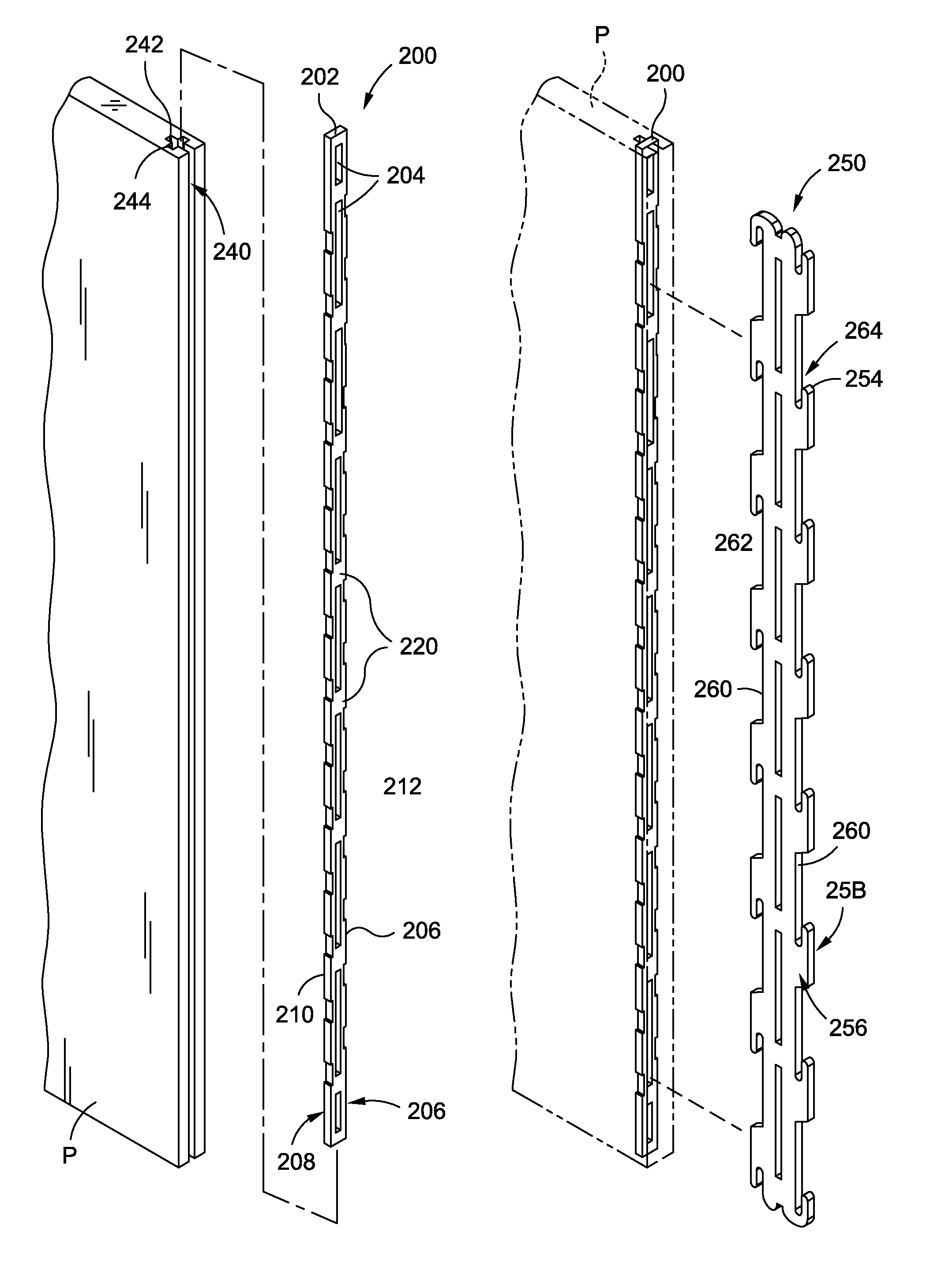
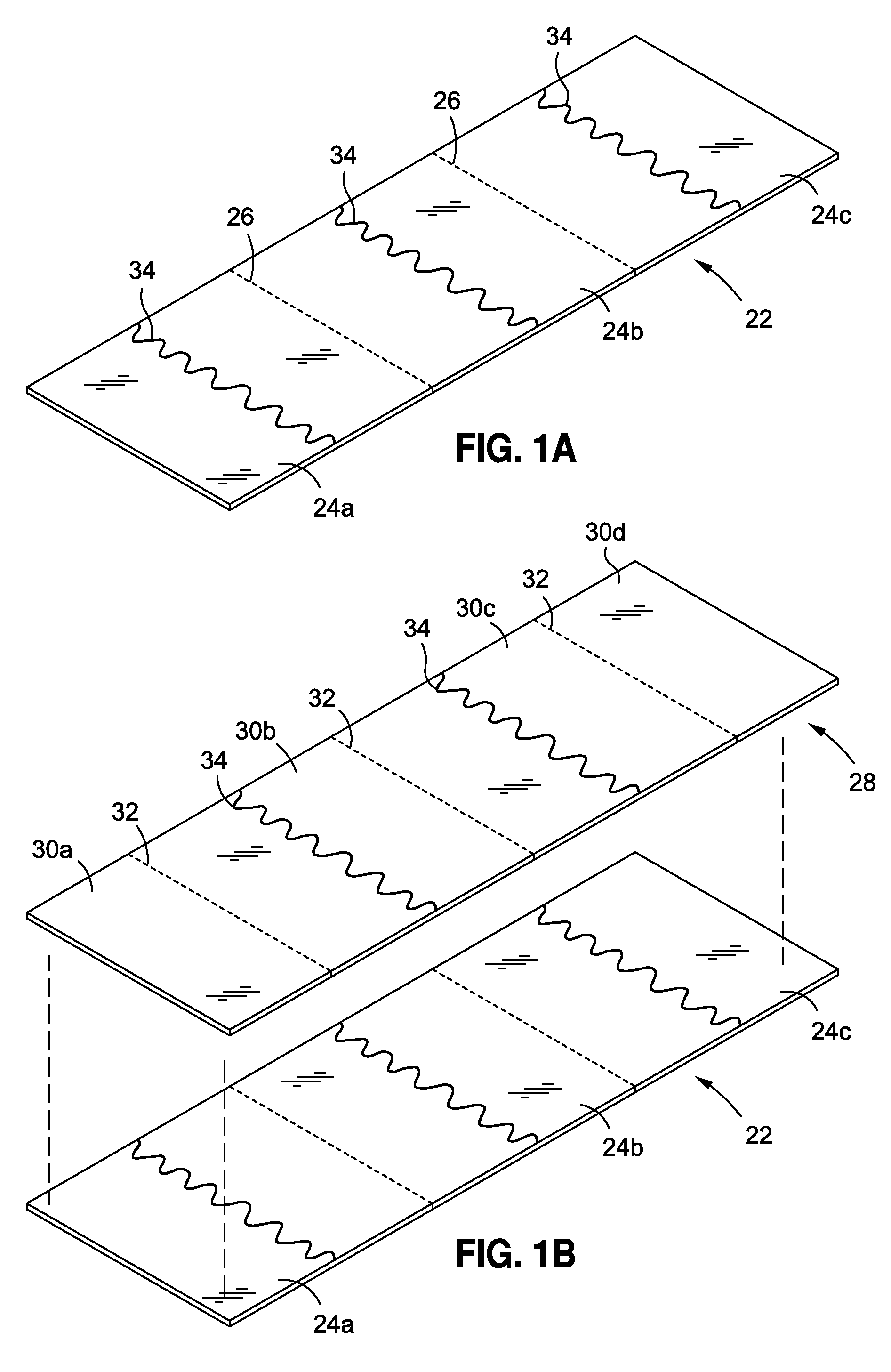
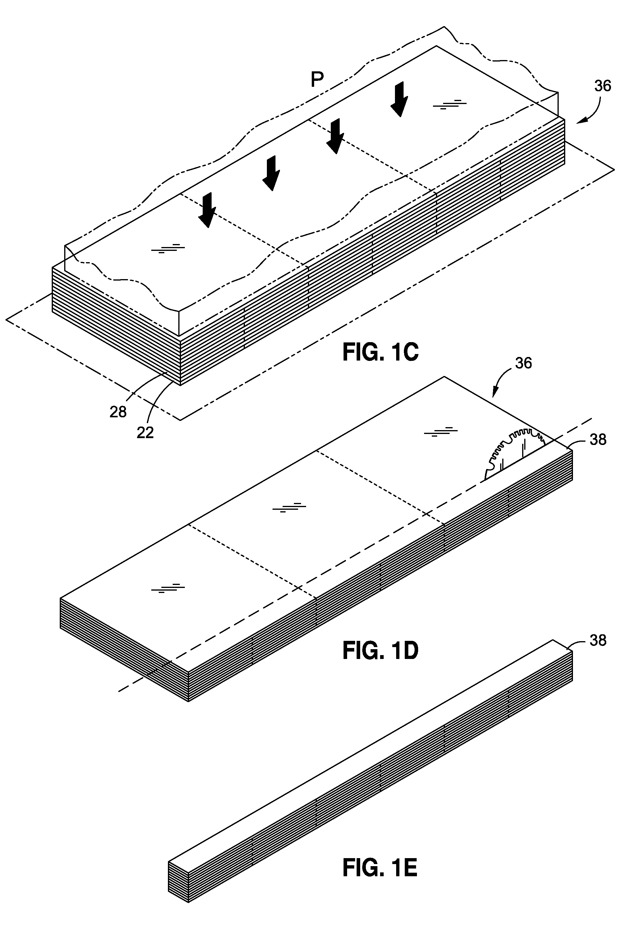
[0049]In general, the panel of the invention has a core and a pair of opposing outer skins. The core preferably emulates a plant-like structure, having a number of structural elements and open spaces or voids. Other aspects of the invention comprise...


PUM

PropertyMeasurementUnit
thicknessaaaaaaaaaa
thicknessaaaaaaaaaa
thicknessaaaaaaaaaa

Abstract

Building or structural panels may be joined, such as to form walls or floors. The panels may be connected in various orientations via one or more connectors. The connectors may mount to anchors associated with the panels. The panels may have outer skins located over an expanded core comprising a matrix of supporting elongate members and voids or openings, with the anchors located at edges of the panels.

Description

RELATED APPLICATION DATA[0001]This application is a continuation-in-part of U.S. patent application Ser. No. 12 / 590,352, filed Nov. 5, 2009 now U.S. Pat. No. 8,322,104, which is a continuation-in-part of U.S. patent application Ser. No. 12 / 584,165, filed Aug. 31, 2009, now U.S. Pat. No. 8,252,137.FIELD OF THE INVENTION[0002]This invention relates to methods and systems for connecting structural or building panels.BACKGROUND OF THE INVENTION[0003]Building panels have a wide variety of configurations. For example, some building panels may comprise solid plywood or particle wood board. These panels are heavy and utilize a substantial volume of material. In addition, such panels are often not very flexible, especially in the case of particle board.[0004]Various attempts have been made to construct other panels which are stronger and lighter in weight. For example, some panels have been constructed from metal. These panels, however, are very expensive both because of the cost of the base...

Claims


Application Information

Patent Timeline
Patent Type & Authority Patents(United States)
IPC IPC(8): E04B2/00E04B2/42
CPCB32B21/08B32B3/10B32B15/10E04C2/36E04C2/38E04C2/00B32B3/08B32B3/06E04B1/6162B32B21/14E04C2/246E04B2001/6195F16B5/0084Y10T403/42Y10T403/44Y10T403/55E04B5/02F16B2200/67E04B1/02E04B1/61E04C2/30E04C2/46E04C2002/001F16B5/0036
Inventor FLEMING, III, JOSEPH, C.
Owner FLEMING III JOSEPH C
Why Eureka
Try Eureka