
Projection lens unit for pico-projector

a projection lens and projector technology, applied in the field of projection lenses for picoprojectors, to achieve the effect of stable focal length

Active Publication Date: 2014-04-08
SEKONIX
View PDF5 Cites 0 Cited by
  • Summary
  • Abstract
  • Description
  • Claims
  • Application Information

AI Technical Summary

Benefits of technology

The invention provides a projection lens unit for a pico-projector that can maintain a stable focal length even when there is heat generated in the pico-projector.

Problems solved by technology

As a display device developed and commercialized as a big screen and high resolution display device, a projector has been rising as one of the most important issues.

Method used


Image

  • Projection lens unit for pico-projector
  • Projection lens unit for pico-projector
  • Projection lens unit for pico-projector

Examples


first embodiment

[0038]FIG. 2 illustrates a lens array 210 of a lens unit for a pico-projector according to the present invention.

[0039]According to the first embodiment of the present invention, the pico-projector comprises a lens array 210, a field lens 250, a cover glass 230 and an image panel 240. The lens array 210 comprises 1st to 5th lenses L1, L2, L3, L4, L5 arranged in order from a screen S onto which an image is projected (that is, the 1st lens L1 is positioned nearest to the screen S and the 5th lens L5 is positioned farthest from the screen S).

[0040]The 1st lens L1 has negative (−) refractive power, the 2nd lens L2 has positive (+) refractive power, the 3rd lens L3 has negative (−) refractive power, the 4th lens L4 has negative (−) refractive power and the 5th lens L5 has positive (+) refractive power. The 1st to 4th lenses L1, L2, L3, L4 are plastic lenses and the 5th lens L5 is a glass lens.

[0041]Table 4 shows the focal lengths of the 1st to 5th lenses L1, L2, L3, L4, L5 of the lens ar...

second embodiment

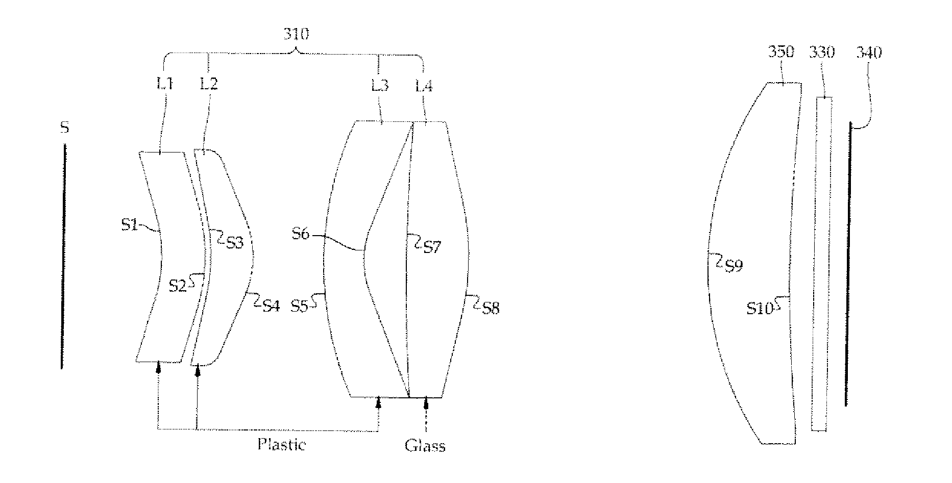
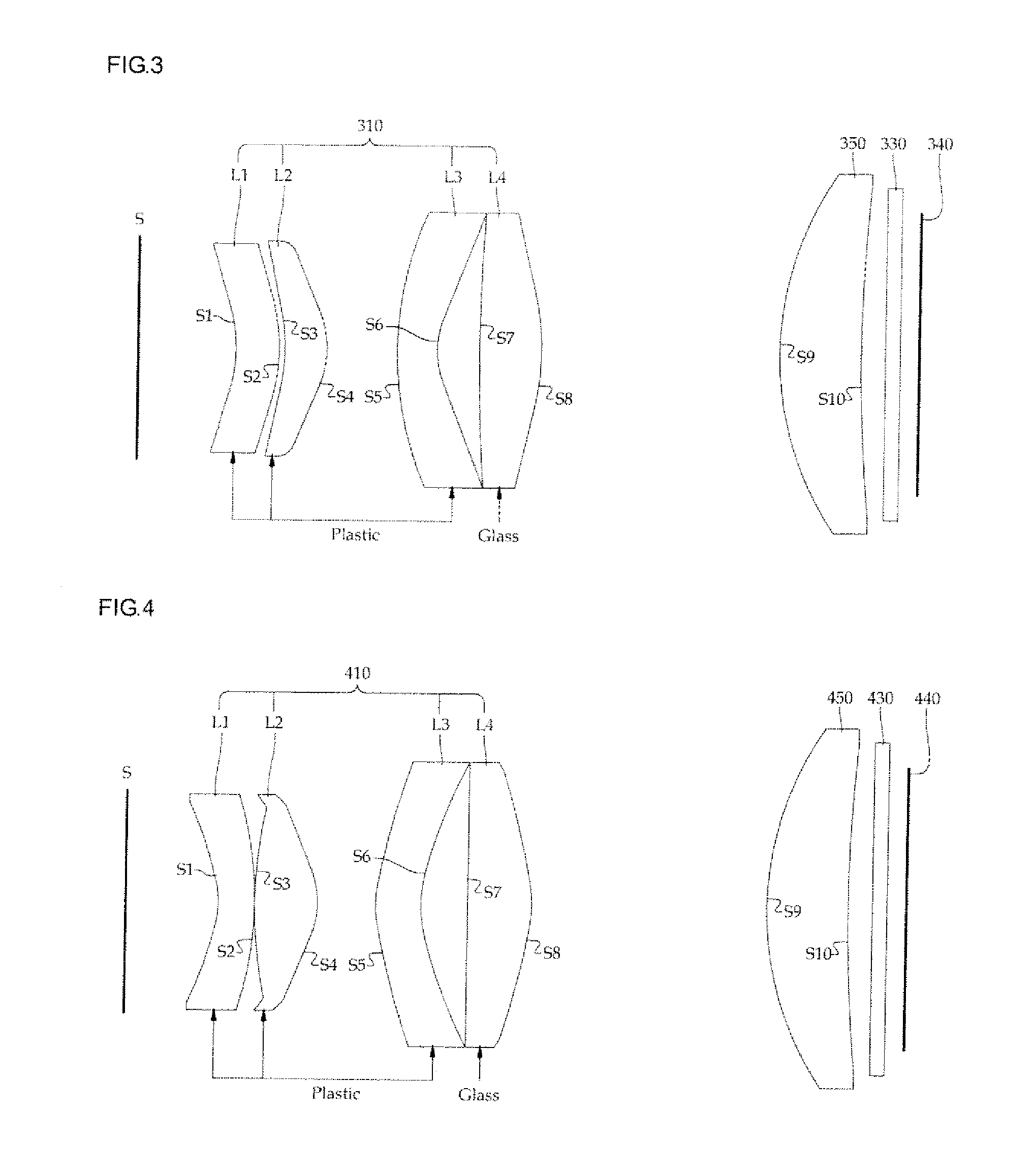
[0048]FIG. 3 illustrates a lens array 310 of a lens unit for a pica-projector according to the present invention.

[0049]According to the second embodiment of the present invention, the pico-projector comprises a lens array 310, a field lens 350, a cover glass 330 and an is image panel 340. The lens array 310 comprises 1st to 4th lenses L1, L2, L3, L4 arranged in order from a screen S onto which an image is projected (that is, the 1st lens L1 is positioned nearest to the screen S and the 4th lens L4 is positioned farthest from the screen S).

[0050]The 1st lens L1 has negative (−) refractive power, the 2nd lens L2 has positive (+) refractive power, the 3rd lens L3 has negative (−) refractive power and the 4th lens L4 has positive (+) refractive power.

[0051]The 1st to 3rd lenses L1, L2, L3 are plastic lenses and the 4th lens L4 is a biconvex glass lens.

[0052]Table 7 shows the focal lengths of the 1st to 4th lenses L1, L2, L3, L4 of the lens array 310 when an internal temperature of the l...

third embodiment

[0059]FIG. 4 illustrates a lens array 410 of a lens unit for a pico-projector according to the present invention.

[0060]According to the third embodiment of the present invention, the pico-projector comprises a lens array 410, a field lens 450, a cover glass 430 and an image panel 440. The lens array 410 comprises 1st to 4th lenses L1, L2, L3, L4 arranged in order from a screen S onto which an image is projected (that is, the lens L1 is positioned nearest to the screen S and the 4th lens L4 is positioned farthest from the screen S).

[0061]The 1st lens L1 has negative (−) refractive power, the 2nd lens L2 has positive (+) refractive power, the 3rd lens L3 has negative (−) refractive power and the 4th lens L4 has positive (+) refractive power.

[0062]The 1st to 3rd lenses L1, L2, L3 are plastic lenses and the 4th lens L4 is a plano-convex glass lens.

[0063]Table 10 shows the focal lengths of the 1st to 4th lenses L1, L2, L3, L4 of the lens array 410 when an internal temperature of the lens...


PUM


Abstract

A projection lens unit for a pica-projector includes a plurality of plastic lenses and a single glass lens to minimize a change in focal length due to the heat generated inside the pico-projector. The lens array includes:a 1st lens with negative (−) refractive power, a 2nd lens with positive (+) refractive power, a 3rd fens with negative (−) refractive power, a 4th lens with negative (−) refractive power, and a 5th lens with positive (+) refractive power, wherein the 1st to 5th lenses are arranged in order from a screen upon which an image is projected, the 1st to 4th lenses are plastic lenses and the 5th lens is a glass lens.

Description

CROSS-REFERENCE TO RELATED APPLICATION[0001]This application claims the benefit of Korean Patent Application No. 2010-0139206, filed Dec. 30, 2010, the disclosure of which is hereby incorporated herein by reference in its entirety.BACKGROUND OF THE INVENTION[0002]1. Field of the Invention[0003]The present invention relates to a projection lens for a pico-projector, and more particularly, to a projection lens for a pico-projector in which a plurality of plastic lenses and a single glass lens are arranged, to minimize a change in focal length due to the heat generated inside the pica-projector.[0004]2. Description of the Related Art[0005]As a display device developed and commercialized as a big screen and high resolution display device, a projector has been rising as one of the most important issues. A projector displays an image by projecting the image formed in a display element by using light emitted by a light source.[0006]A very small projector has been developed in the name of a...

Claims


Application Information

Patent Timeline
Patent Type & Authority Patents(United States)
IPC IPC(8): G02B9/34
CPCG02B3/0006G02B7/028G02B13/0045G03B21/14
Inventor LEE, HEE-JOONGKIM, JIN-HOHWANG, SUNG-HOONHONG, SEUNG-KI
Owner SEKONIX
Learn More