LED explosion-proof lighting lamp convenient to overhaul

A technology for lighting lamps and lamps, which is applied in the field of explosion-proof lamps and can solve the problems of inconvenient maintenance of explosion-proof lamps

Active Publication Date: 2022-04-29
华荣照明有限公司
View PDF13 Cites 0 Cited by
  • Summary
  • Abstract
  • Description
  • Claims
  • Application Information

AI Technical Summary

Problems solved by technology

[0006] Aiming at the deficiencies of the prior art, the present invention provides an LED explosion-proof lighting fixture that is easy to overhaul, has the advantages of convenient overhaul, etc., and solves a series of problems such as inconvenient overhaul when the explosion-proof lamp fails in the prior art.

Method used


Image

  • LED explosion-proof lighting lamp convenient to overhaul
  • LED explosion-proof lighting lamp convenient to overhaul
  • LED explosion-proof lighting lamp convenient to overhaul

Examples


Embodiment 1

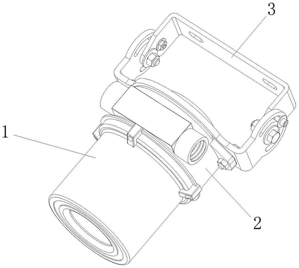
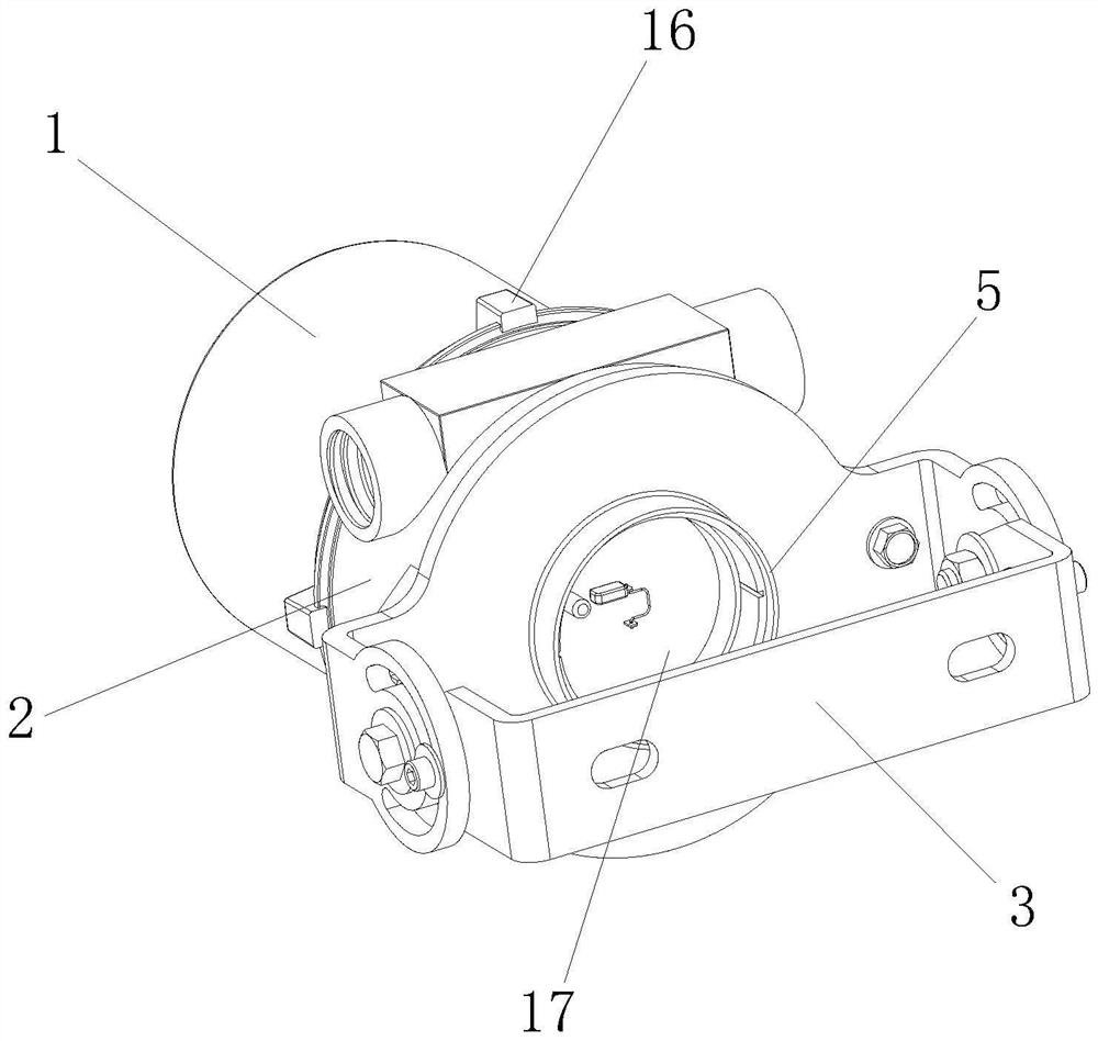
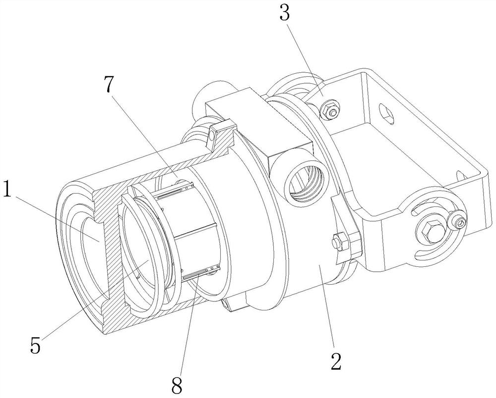
[0040] Such as Figure 1-10 As shown, an LED explosion-proof lighting fixture that is convenient for maintenance includes a lamp housing. The lamp housing includes a lamp holder 2 for installing LED explosion-proof lamp beads and a lampshade 1 that is interlocked with the lamp holder 2. The lamp holder 2 also contains There is a sliding tube 5 slidingly socketed with it, and a mounting seat 17 is slidingly socketed in the sliding tube 5, and an LED explosion-proof lamp bead and a transformer circuit electrically connected to each other are installed on the mounting seat 17. There is a first electromagnet 4 connected in series with the transformer circuit, the LED explosion-proof lamp bead and the first electromagnet 4 are installed on the output side of the transformer circuit, the input side of the transformer circuit and the external power supply circuit can form a power loop, and the sliding One end of the tube 5 corresponding to the first electromagnet 4 is also connected ...

Embodiment 2

[0042] Compared with the above-mentioned embodiments, the difference between this embodiment is that: refer to the appended Figure 11 , S1 represents the first electromagnet 4, S2 represents the second electromagnet, and R represents the resistance;

[0043] The external power supply line is also electrically connected to the second electromagnet in parallel with the first electromagnet 4, and the input side and output side of the second electromagnet are respectively connected to the input side of the first electromagnet 4 and the output of the LED explosion-proof lamp bead. side, the second electromagnet is installed inside the lampshade 1 and corresponds to the position of the first electromagnet 4, and there is also a switch that can control the second electromagnet to be energized between the output side of the second electromagnet and the connection position of the external power supply line. The switch is installed on the lamp shell, and the magnetic field strength for...


PUM


Abstract

The invention relates to the field of explosion-proof lamps, and discloses an LED explosion-proof lighting lamp convenient to overhaul, which comprises a lamp holder for mounting LED explosion-proof lamp beads and a lampshade clamped with the lamp holder, and the input side of a transformation circuit and an external power supply circuit can form a power-on loop. The end, corresponding to the first electromagnet, of the sliding barrel is further connected with a metal ring matched with the first electromagnet, and when the first electromagnet is powered off, the driving spring can enable the sliding barrel, the LED anti-explosion lamp bead and the voltage transformation circuit to actively extend out of the lamp holder. According to the LED explosion-proof lamp, when the LED explosion-proof lamp bead goes out in the using process, the bearing piece provided with the LED explosion-proof lamp bead does not need to be screwed out, the maintenance time is saved, secondly, when the LED explosion-proof lamp bead goes out, the function of automatically judging the disconnection position is achieved, whether a power-on circuit or the LED explosion-proof lamp bead goes out is rapidly determined, and the maintenance efficiency is improved. And the interiors of the lamps do not need to be dismounted for one-by-one checking during maintenance, so that the maintenance efficiency is further improved.

Description

technical field [0001] The invention relates to the field of explosion-proof lamps, in particular to an LED explosion-proof lighting fixture which is convenient for maintenance. Background technique [0002] The LED explosion-proof lamp is a kind of explosion-proof lamp. Its principle is the same as that of the explosion-proof lamp, except that the light source is an LED light source. Measure luminaires. [0003] Due to the special working environment of explosion-proof lamps, for safety needs, explosion-proof lamps need to be disassembled regularly for maintenance and repair, and the operation of the existing explosion-proof lamp maintenance process is relatively cumbersome. Among them, a Chinese patent document with the publication number CN110715203B proposes a convenient The installation and disassembly of dust gas LED explosion-proof lights, although it can realize the convenient installation and removal of LED explosion-proof lights. [0004] However, when the above-...

Claims


Application Information

Patent Timeline
Patent Type & Authority Applications(China)
IPC IPC(8): F21V25/04F21V19/00F21V21/00F21V19/02F21V14/02F21Y115/10
CPCF21V25/04F21V19/003F21V21/00F21V19/02F21V14/02F21Y2115/10
Inventor 何金田
Owner 华荣照明有限公司
Why Eureka
Try Eureka