

Collimating lens and projection module
A lens and collimation technology, applied in the field of camera lens, can solve the problems of low yield, larger image point, difficult production and processing, etc., and achieve the effect of low cost and stable focal length
- Summary
- Abstract
- Description
- Claims
- Application Information
AI Technical Summary
Problems solved by technology
Method used
Image

Examples
no. 1 example
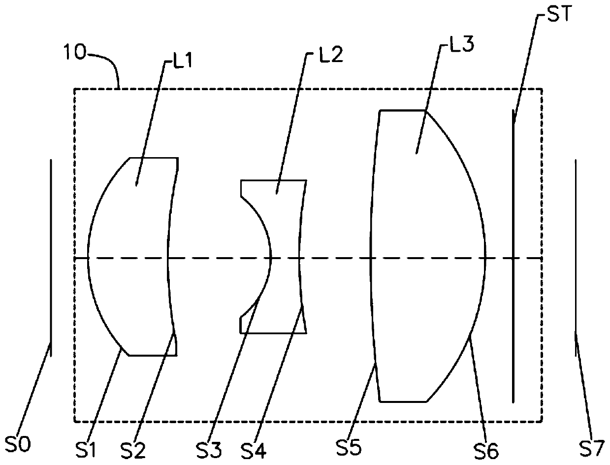
[0087] see figure 1 , a schematic structural diagram of a collimating lens 10 provided in this embodiment, the laser emitter end is set as the object side S0, the measured object end is the image side S7, and the sequence from the object side S0 to the image side S7 includes: the first lens L1, second lens L2, third lens L3 and stop ST.
[0088] The first lens L1 has positive refractive power, the object side S1 of the first lens L1 is a convex surface, and the image side S2 of the first lens L1 is a concave surface.
[0089] The second lens L2 has negative refractive power, and both the object side S3 and the image side S4 of the second lens L2 are concave.
[0090] The third lens L3 has positive refractive power, the object side S5 of the third lens L3 is concave and the image side S6 is convex.
[0091] The stop ST is located between the third lens L3 and the object to be measured. The optical centers of each lens are located on the same straight line, and each lens is m...
no. 2 example
[0105] The structural representation of the collimating lens 20 of the present embodiment can refer to Figure 5 . This embodiment is roughly similar to the lens structure diagram of the first embodiment, except that the relevant parameters of each lens are different.
[0106] The relevant parameters of each lens in the collimating lens 20 in this embodiment are shown in Table 3.
[0107] table 3
[0108] Surface serial number surface type r d n d
Vd object plane S0 sphere — 0.420 S1 first lens Aspherical 0.646 0.395 1.640 23.529 S2 Aspherical 1.289 0.823 S3 second lens Aspherical -0.513 0.266 1.516 57.038 S4 Aspherical 14.889 0.657 S5 third lens Aspherical 5.288 0.525 1.640 23.529 S6 Aspherical -1.233 0.350 ST aperture sphere — 300.000 S7 Image surface sphere — —
[0109] The aspherical parameters of each lens in this embodiment...
no. 3 example
[0115] The structural representation of the collimating lens 30 of the present embodiment can refer to Figure 9 , this embodiment is roughly similar to the lens structure diagram of the first embodiment, except that the relevant parameters of each lens are different.
[0116] The relevant parameters of each lens in the collimating lens 30 in this embodiment are shown in Table 5.
[0117] table 5
[0118] Surface serial number surface type r d n d
Vd object plane S0 sphere — 0.250 S1 first lens Aspherical 0.647 0.524 1.640 23.529 S2 Aspherical 1.412 0.592 S3 second lens Aspherical -0.726 0.170 1.640 23.529 S4 Aspherical 1.232 0.773 S5 third lens Aspherical 21.774 0.641 1.640 23.529 S6 Aspherical -1.054 0.400 ST aperture sphere — 300.000 S7 Image surface sphere — —
[0119] The aspheric parameters of each lens in this embodiment ar...
PUM
| Property | Measurement | Unit |
|---|---|---|
| optical path length | aaaaa | aaaaa |
Abstract
Description
Claims
Application Information