Vehicle seat

a technology for vehicles and seats, applied in the field of vehicles seats, can solve the problems of poor attachment stability, use of technology, and weak engagement force of the support structure with respect to the frame member, and achieve the effects of excellent attachment stability, easy attachment and easy disassembly

Active Publication Date: 2014-04-15
TOYOTA BOSHOKU KK
View PDF21 Cites 19 Cited by
  • Summary
  • Abstract
  • Description
  • Claims
  • Application Information

AI Technical Summary

Benefits of technology

[0008]The invention thus provides a vehicle seat in which a support member is able to be compactly attached to and detached from a frame member, while maintaining the attachment stability.
[0011]Then, the first attaching portion is overlapped with the second attaching portion (from the sitting side of the seat). Then the first engaging portion is abutted against a first edge of the other portion and the second engaging portion is abutted against a second edge of the other portion that is different from the first edge. Furthermore, one of the first engaging portion or the second engaging portion is hooked onto the engagable portion such that the support member is attached to (i.e., engaged with) the frame member. In this aspect, the support member is able to be engaged (compactly) with the frame member from the sitting side of the seat. Also, when engaging the support member with the frame member, the first engaging portion or the second engaging portion hooks onto the engagable portion, while the other portion is gripped by the first engaging portion and the second engaging portion. That is, this structure provides excellent attachment stability.
[0012]In the vehicle seat according to the aspect described above, the first engaging portion and the second engaging portion may be alternately arranged along an outer shape of one portion of the first attaching portion or the second attaching portion. Alternately arranging the first engaging portion and the second engaging portion enables the other portion to be held with an appropriate amount of gripping force. Therefore, the other portion can be relatively easily attached between the first engaging portion and the second engaging portion, as well as relatively easily detached from those engaging portions. That is, this structure provides excellent attachability and detachability.
[0013]According to this aspect of the invention, the support member is able to be compactly attached to and detached from the frame member, while maintaining the utmost attachment stability. Also, the attachability and detachability of the support member can be improved.

Problems solved by technology

This presents difficulties, such as the support member hitting another member such as the ceiling or the like, for example, when attaching the frame member while inside the vehicle.
Also, with the technology described in Japanese Patent No. 4069307, the support member is retained by the engagement of the protruding portion in the groove portion (i.e., by one type of engaging structure), so the engaging force of the support structure with respect to the frame member is somewhat weak.
That is, the structure provides fairly weak attachment stability.
Therefore, the technology described in Japanese Patent No. 4069307 is simply unable to be used with the technology described in Japanese Patent No. 4228355, considering the attachment stability and workability and the like.

Method used


Image

  • Vehicle seat
  • Vehicle seat
  • Vehicle seat

Examples


Embodiment Construction

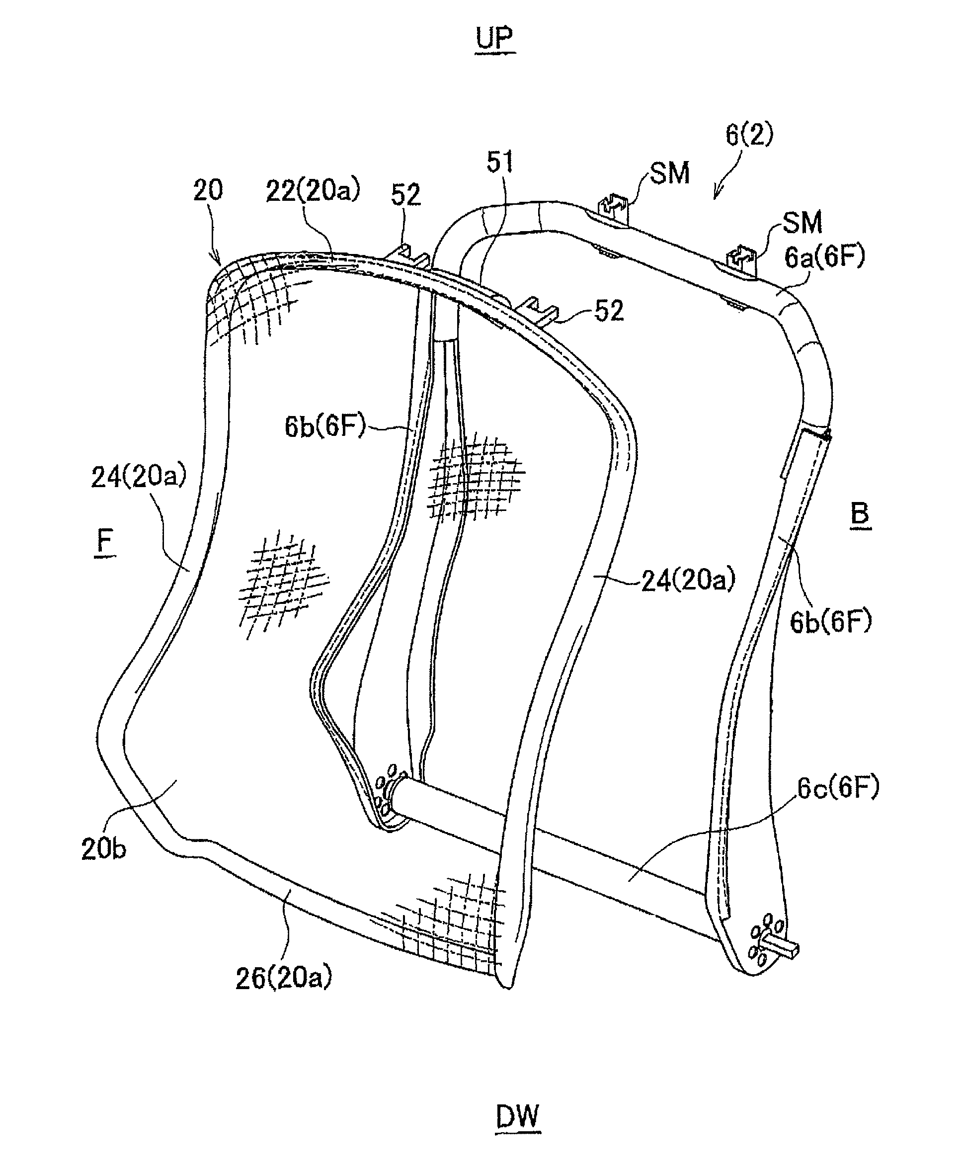
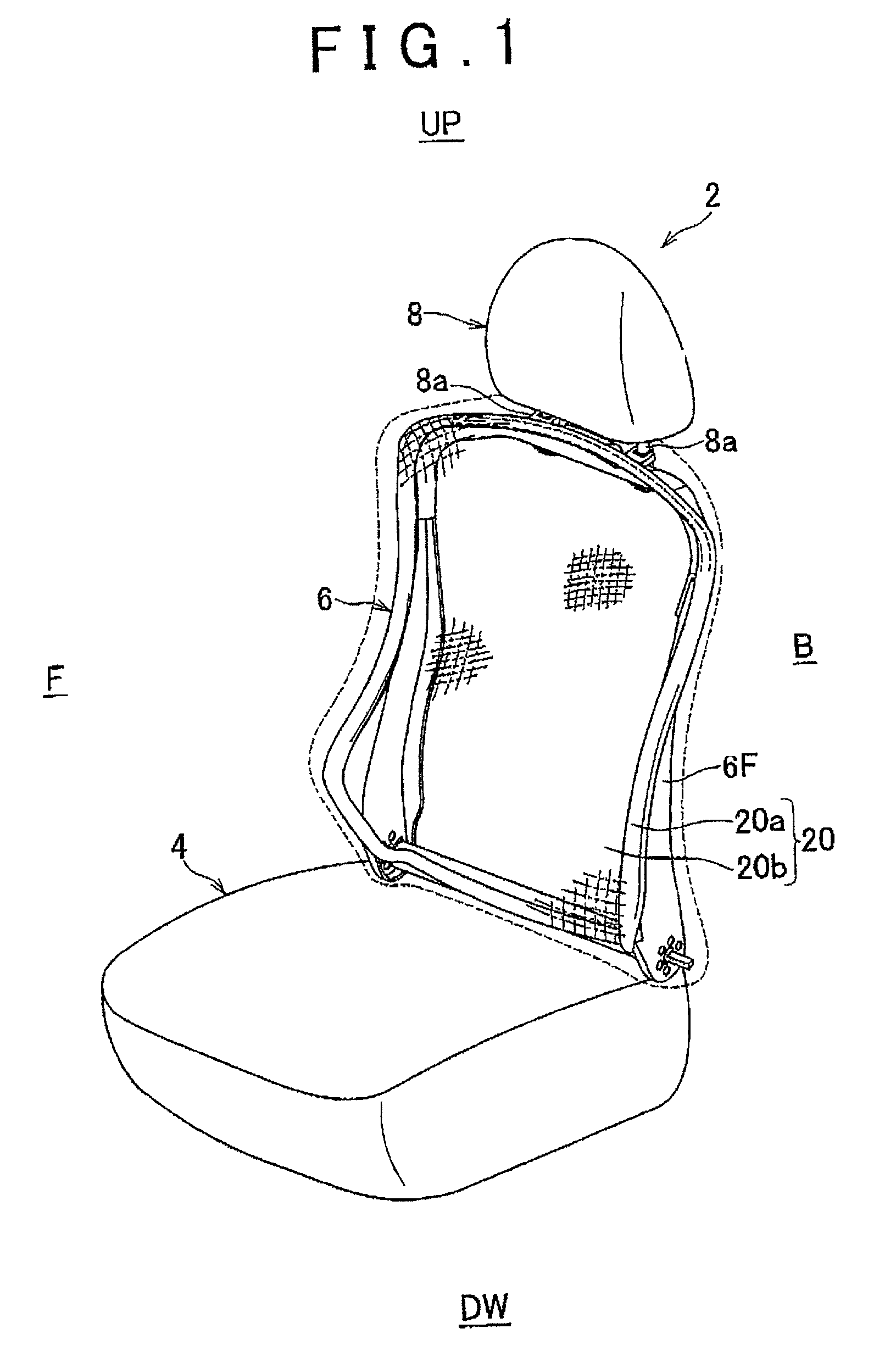
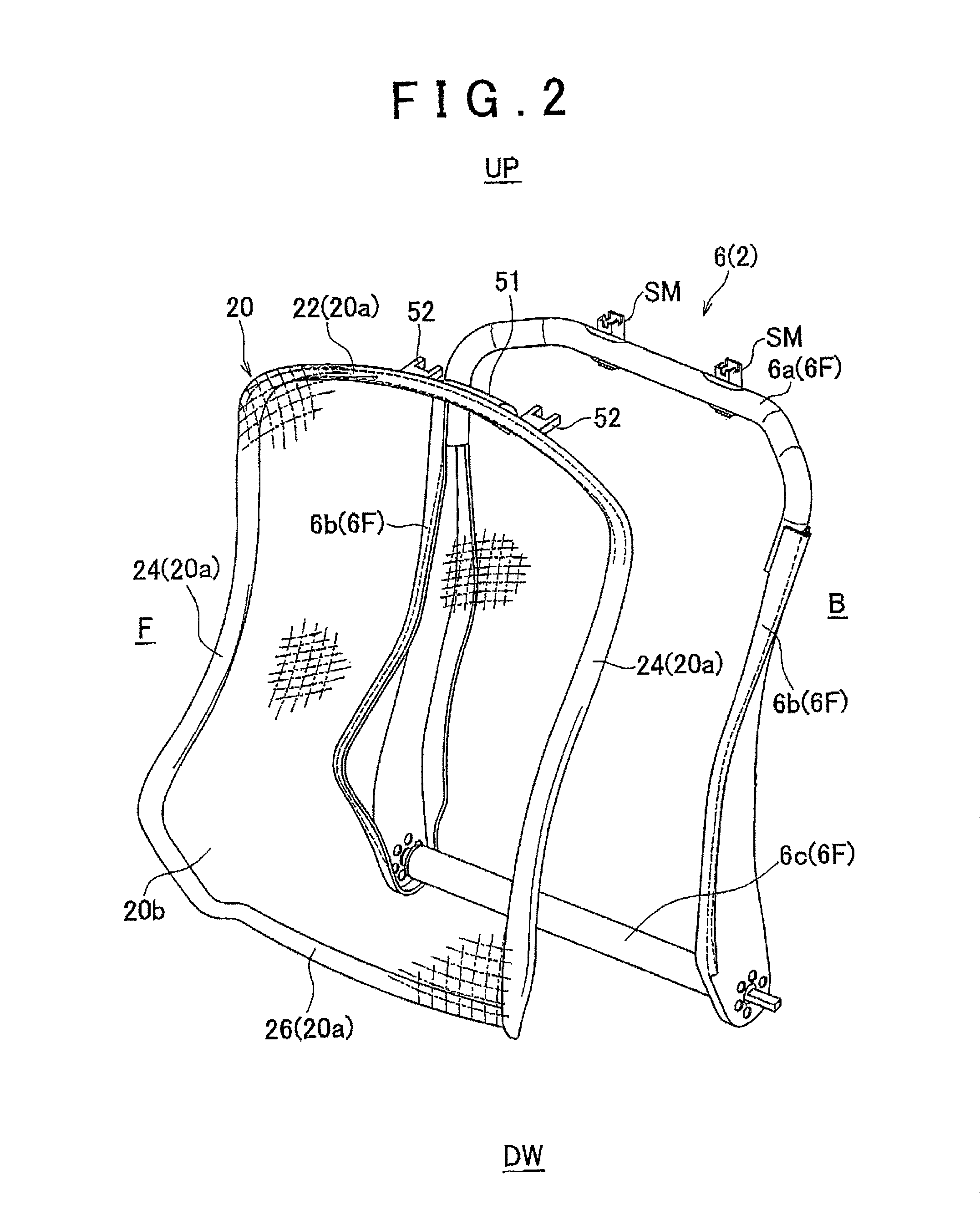
[0022]Hereinafter, example embodiments of the invention will be described with reference to FIGS. 1 to 7. In the drawings, reference character F denotes a forward direction with respect to the vehicle seat, reference character B denotes a backward or rearward direction with respect to the vehicle seat, reference character UP denotes an upward direction with respect to the vehicle seat, and reference character DW denotes a downward direction with respect to the vehicle seat. A vehicle seat 2 in FIG. 1 has a seat cushion 4, a seat back 6, and a headrest 8 (all of which are examples of a seat structure member). The headrest 8 has a pair of stay members 8a and is attached to an upper portion of the seat back 6. The pair of stay members 8a are rod-shaped members that are arranged in parallel a predetermined distance apart from each other on a lower portion of the headrest 8.

[0023]The seat back 6 is a member that is reclinably connected to the seat cushion 4 (see FIGS. 1 to 3 and 6). The ...


PUM


Abstract

An engaging structure has a first engaging portion and a second engaging portion provided on at least one portion from among a first attaching portion and a second attaching portion, and an engagable portion provided on another portion that is different from the one portion. The first attaching portion is overlapped with the second attaching portion such that the first engaging portion abuts against a first edge of the other portion and the second engaging portion abuts against a second edge of the other portion that is different from the first edge. A support member is engaged with a frame member by one of the first engaging portion or the second engaging portion being hooked onto the engagable portion.

Description

INCORPORATION BY REFERENCE[0001]The disclosure of Japanese Patent Application No. 2010-128742 filed on Jun. 4, 2010 including the specification, drawings and abstract is incorporated herein by reference in its entirety.BACKGROUND OF THE INVENTION[0002]1. Field of the Invention[0003]The invention relates to a vehicle seat that includes a frame member and a support member (i.e., a member that supports an occupant) that is attached to the frame member.[0004]2. Description of the Related Art[0005]Japanese Patent No. 4228355 describes one such vehicle seat. This vehicle seat includes a seat cushion and a seat back that is connected in an upright position to the seat cushion. The seat cushion includes a frame member and a support member. The frame member is a generally rectangular frame-shaped member that forms a seat frame and includes an upright piece. This upright piece is a flat plate member that extends in the longitudinal direction of the seat, and is arranged on an upper surface (a...

Claims


Application Information

Patent Timeline
Patent Type & Authority Patents(United States)
IPC IPC(8): A47C7/02A47C7/42A47C7/00B60N2/90
CPCB60N2/72B60N2/682B60N2/7011B60N2/686
Inventor MIZOBATA, HIROSHI
Owner TOYOTA BOSHOKU KK
Why Eureka
Try Eureka