Container assembly with supplementary support structure

a technology of supporting structure and container, applied in the field of container assembly, can solve the problems of inconvenient transportation of one or more additional containers, poor biodegradable characteristics of recycled materials, and the inconvenience of having to transport all of the collected refuse or garbage,

Inactive Publication Date: 2005-10-11
MALLOY III JOHN CYRIL
View PDF32 Cites 28 Cited by
  • Summary
  • Abstract
  • Description
  • Claims
  • Application Information

AI Technical Summary

Benefits of technology

[0013]In one preferred embodiment of the present invention, the supplementary support structure of the container assembly comprises a support platform, described in greater detail hereinafter, which is movably mounted on the housing so as to be selectively positionable between an operative position and a stored position. The supplementary support structure is preferably permanently mounted to the housing but could also take the form of an after market, attachment device which is easily mounted on and removed from the housing. The operative position is preferably defined at least in part by the preferred support platform extending outwardly from a sidewall or other exterior portion of the housing, ideally in a generally transverse orientation. In the stored position, the preferred support platform preferably assumes a substantially collapsed or retracted position, wherein the support platform takes up relatively little or almost no additional space, other than that occupied by the housing of the container assembly itself. Further, when in its operative position, and virtually regardless of the specific preferred embodiment of the container assembly of the present invention contemplated, the support platform is independently structured and cooperatively secured to the housing so as to support at least a predetermined amount of weight, such as that generally equivalent to a weight typically associated with one or more specialized storage bins carrying a collection of recyclable materials. As set forth above, such materials may include but are not limited to newspapers, plastics, glass bottles or jars, aluminum and metal cans, etc. While in its operative position, the support platform preferably extends substantially transversely outward from an exterior portion of the housing at what may be considered a generally perpendicular angle to a central longitudinal axis of the container. It should be noted, however, that the support platform may extend outwardly at other preferred angles which serve to maintain the additional container or bins of recyclable materials on the support platform, exteriorly of the housing, particularly when the container assembly of the present invention is being moved across the ground or other supporting surface, as intended. In order to reduce the possibility of such containers or other materials inadvertently falling off the support platform, particularly during transport of the container assembly, additional retainer structures, such as but not limited to a upstanding lip or flange, may be formed on or associated with the support platform. As briefly mentioned above, the stored position may be defined by the supplementary support structure being disposed in an immediately adjacent, overlying disposition and / or in a substantially aligned or generally parallel orientation relative to an exposed surface of a sidewall of the housing. To achieve movement between the operative and stored positions, the supplementary support structure is, in the most preferred embodiment, pivotally or otherwise movably connected, such as at one end thereof, to the exterior of the housing, such that the support platform may be easily positioned into the outwardly extended operative position or into the stored position relative to a sidewall of the housing.
[0021]Yet another object of the present invention is to provide a mobile container assembly specifically, but not exclusively, designed for the temporary storage and transport of waste or refuse material, and which in one embodiment incorporates a supplementary support structure which is permanently, but not necessarily integrally or fixedly attached to the exterior thereof, in a manner which eliminates the necessity for selective attachment or detachment of a support platform to the exterior of the container assembly.

Problems solved by technology

Typically, materials which are recycled demonstrate poor biodegradable characteristics and include glass, plastics, aluminum cans, other products made of metal, etc.
While such waste collection systems are thought to offer a vast improvement over those of eras gone by, in terms of helping to avoid both disease and pestilence problems associated with rotting garbage, there is still an inconvenience associated with having to transport all of the collected refuse or garbage, including recyclable items, to the curb side or other location for pick up.
While such known refuse containers alleviate somewhat the inconvenience associated with transporting the collected waste to the curb or other location for disposal, there still remains the problem of having to transport the one or more additional containers used to collect recyclable objects, which are maintained separately from those waste materials not intended to be recycled and which are usually just deposited into a conventional garbage can.
However, even these more specialized carrier devices for recyclable items still require that an individual make more than one trip from his or her home to the garbage pick-up site because of the fact that the conventional garbage containers, wherein the general, non-recyclable waste materials are deposited, must also be transported to the curb of other location for pick-up given that in many communities, trash pick up of both recyclable and non-recyclable waste occurs on the same day.
On the other hand, even this type of device suffers from certain inherent disadvantages which render it somewhat impractical.
Specifically, it is believed that the known attachment structures require some adjustment in order to hold or carry a recycling bin, that they also make it difficult to load and unload a bin which is full of recyclable waste, and further, that it is necessary to attach and remove such attachment structures from the conventional refuse container each time a trip is made to or from the curb side location.
As such, the known after market, add-on attachment devices do not satisfactorily address the convenience issues discussed above, and therefore, might not be used on a consistent basis.
In addition, such after market, attachment devices are not structurally adapted to be mounted on all of the large variety of conventional refuse containers, most of which have a different design, size and / or configuration.
Moreover, it is not uncommon for a user to own more than one type of conventional garbage container, with the result that the known, after market, add-on devices would be highly unlikely to be mounted on each of the refuse containers owned by a user.
As a result of the inconveniences associated with the separate collection of a variety of different waste materials, and the fact that devices known in the art fail to adequately overcome those inconveniences, there are many individuals who do not follow the appropriate and intended procedures for separating from general domestic waste material those materials deemed by a community to be easily recycled and worthy of a concentrated recycling program.
Consequently, although efforts are underway to cause less harm to the environment by way of recycling selected items, including non-biodegradable waste, these efforts are being impeded by the fact that there remain a few fairly significant inconveniences associated with the collection and disposal of domestic waste, even when it has been separated into recyclable items.

Method used


Image

  • Container assembly with supplementary support structure
  • Container assembly with supplementary support structure
  • Container assembly with supplementary support structure

Examples


Embodiment Construction

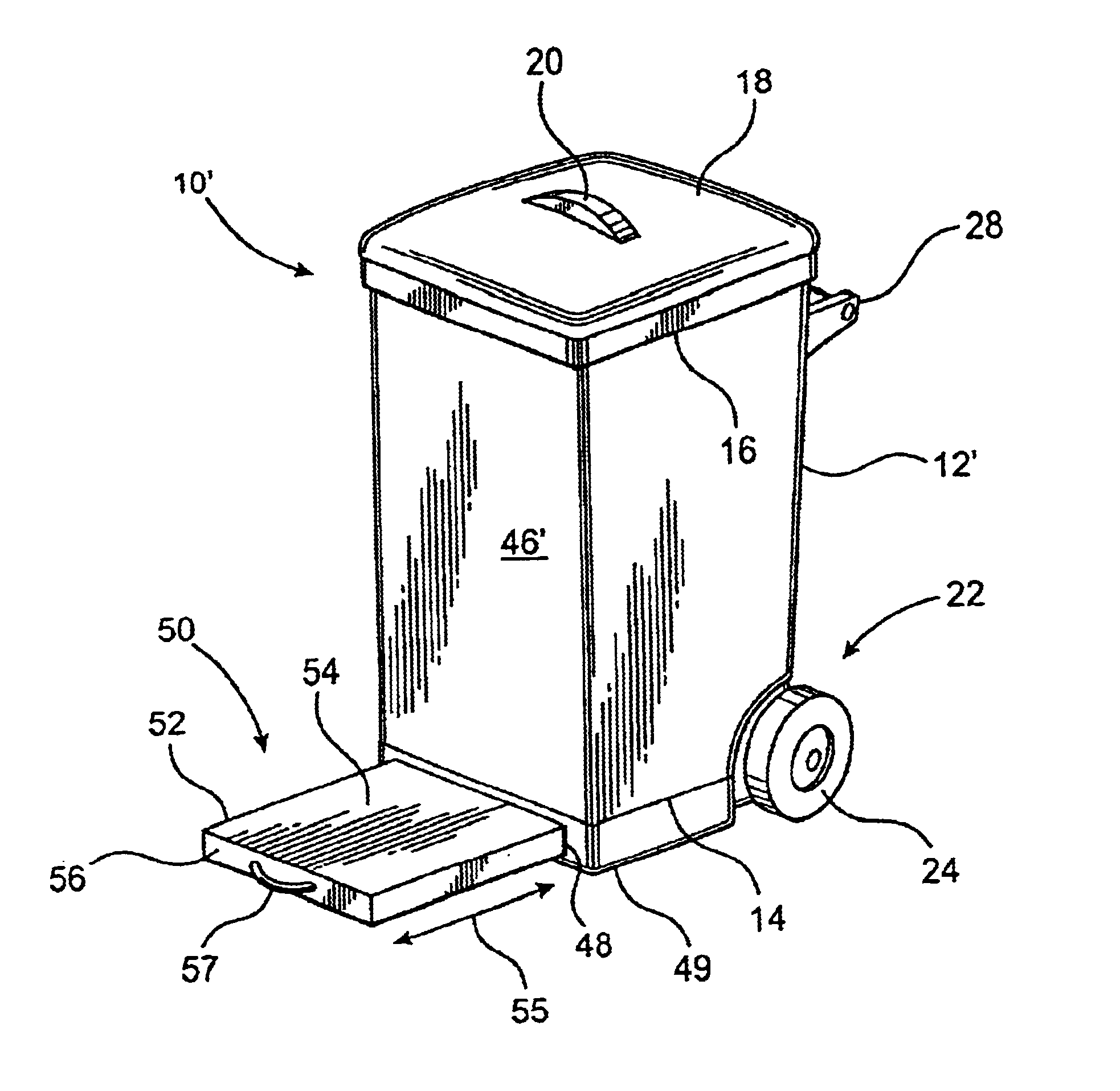
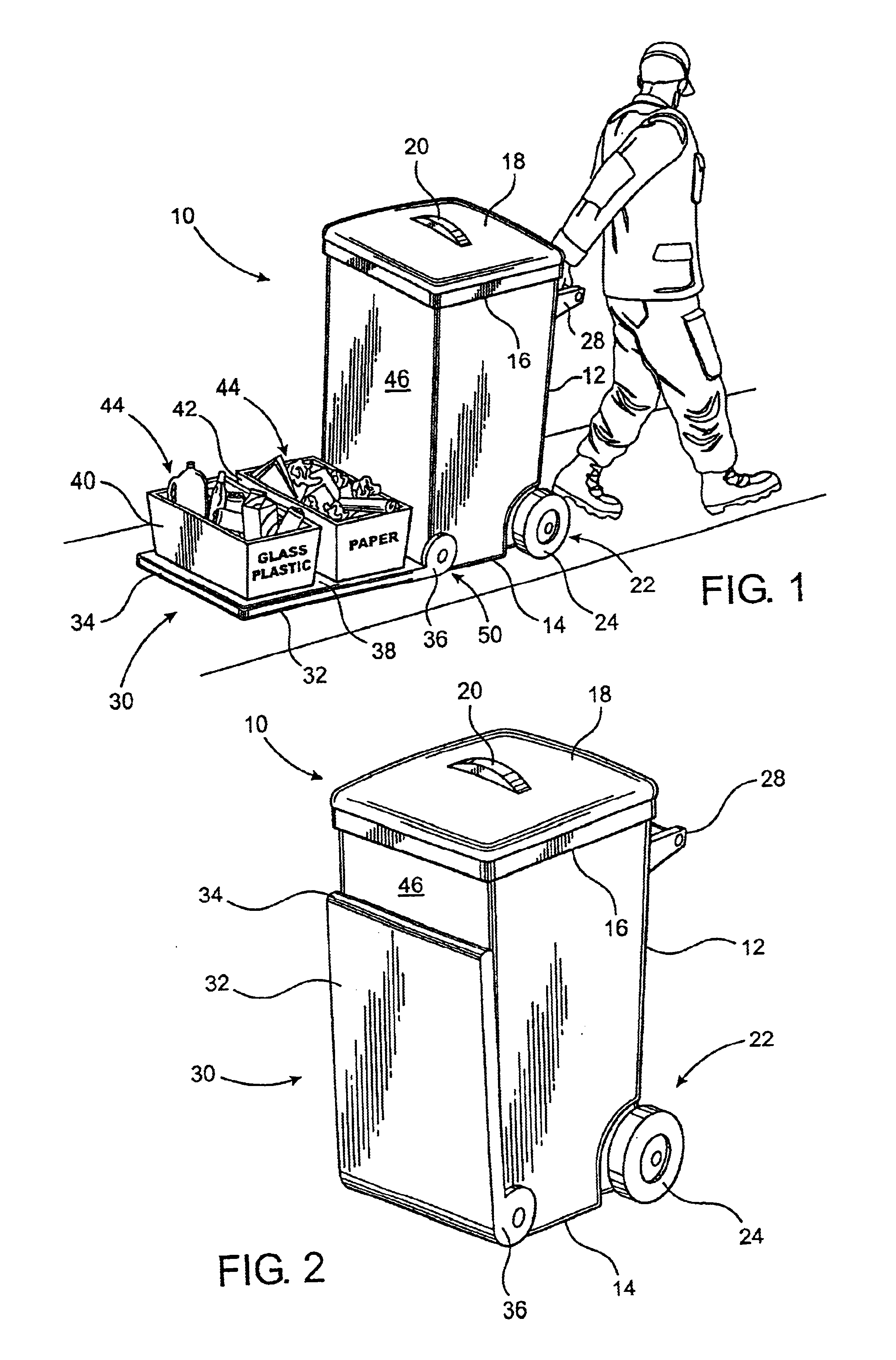
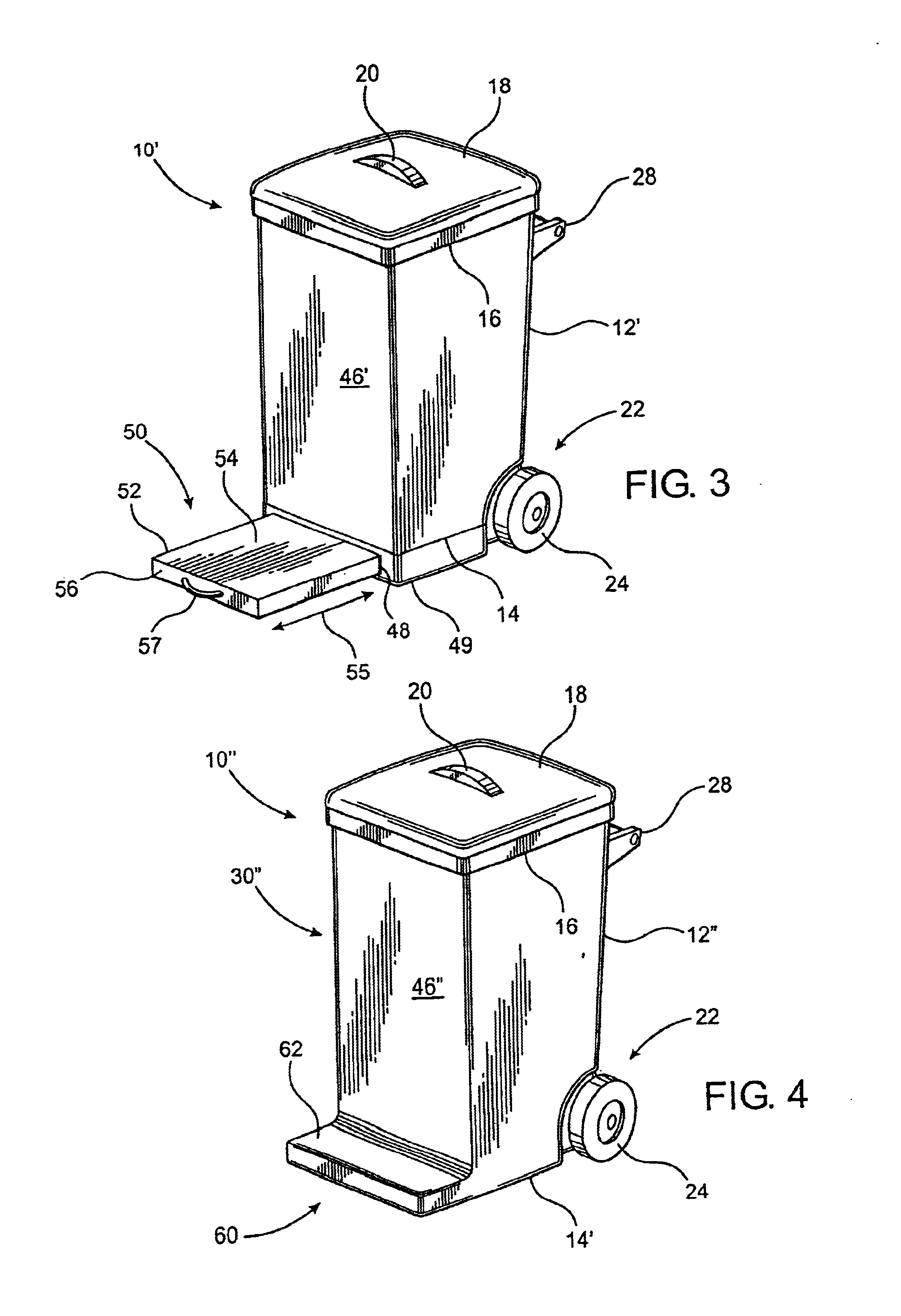
[0033]As shown in the accompanying Figures, the present invention is directed towards a container assembly, indicated generally by reference numeral 10 in FIGS. 1 and 2, which is primarily, but not exclusively, intended for use in collecting, storing and transporting a variety of trash or garbage. The container assembly, generally indicated as 10, includes a housing 12 having a hollow interior and a closed end portion 14, which preferably, but not necessarily is located at the bottom end of the housing 12. The container assembly also includes an access opening 16 which communicates with the hollow interior of the housing, and which preferably is disposed at the opposite end of the housing 12. The access opening 16 is dimensioned and configured to facilitate the deposit and removal of a variety of materials or objects into and out of the hollow interior for the collection, temporary storage and eventual removal thereof. A lid structure 18 is preferably also provided, which ideally, i...


PUM


Abstract

A container assembly designed for the collection, temporary storage and transport of refuse, waste material or other objects including a housing having a hollow interior in which the refuse is collected and stored and further including a supplementary support structure movably mounted on the housing and selectively positionable between an operative position and a stored position. The supplementary support structure is at least partially defined by a support platform which, when in the operative position, extends outwardly from a sidewall or other exterior surface portion of the housing and is structured to support and have mounted thereon one or more objects or containers of additional refuse material, etc. such that diverse objects or materials may be stored and transported both interiorly of the housing and exteriorly thereof, thereby increasing the capacity of the materials or objects stored on and transported by the container assembly while maintaining the objects or materials in a segregated relation to one another. The supplementary support structure, in certain embodiments of the present invention, may be disposed in a retracted orientation to define the stored position when the storage or transport of objects or materials on the exterior of the housing is not intended or required. Further, the housing is at least partially tapered such that at least two container assemblies can be concentrically stacked within one another when the supplementary support is in its stored position.

Description

CLAIM OF PRIORITY[0001]The present application is a continuation application of previously filed application having Ser. No. 10 / 156,460, which was filed on May 28, 2002 now abandoned which is also a continuation application of previously filed now abandoned application having Ser. No. 09 / 947,066, which was filed on Sep. 5, 2001, which is a divisional application of previously filed, now abandoned application having Ser. No. 09 / 294,648, filed on Apr. 19, 1999.BACKGROUND OF THE INVENTION[0002]1. Field of the Invention[0003]The present invention relates to a container assembly designed to store and transport garbage, waste and / or other types of materials. More in particular, the container assembly of the present invention is structured to store and permit the transport of waste and related objects in a segregated fashion by maintaining a first variety of collected materials on the interior of the container assembly and at least a second variety of collected objects exteriorly thereof, ...

Claims


Application Information

Patent Timeline
Patent Type & Authority Patents(United States)
IPC IPC(8): B65F1/14
CPCB65F1/1468B65F2210/18B65F2220/12Y10S220/908
Inventor MALLOY, III, JOHN CYRIL
Owner MALLOY III JOHN CYRIL
Why Eureka
Try Eureka