Viscous fan drive systems having fill and scavenge control

a fan drive and viscous technology, applied in the direction of water supply installation, fluid coupling, coupling, etc., can solve the problems of fan drive engagement, disengagement, adverse effects on pumpout performance, especially at low input speed, and inherently limited modulation robustness of fan drive, etc., to achieve the effect of overcoming or minimizing the disadvantages of the fan driv

Inactive Publication Date: 2014-04-22
BORGWARNER INC
View PDF13 Cites 4 Cited by
  • Summary
  • Abstract
  • Description
  • Claims
  • Application Information

AI Technical Summary

Benefits of technology

[0010]The present invention is an improvement over known fan drives and minimizes or overcomes their disadvantages.
[0013]The embodiments of the present invention provide several advantages. One such advantage is the incorporation of a mechanism for directly controlling the flow of fluid exiting a working chamber of a fluid-coupling device. This provides for efficient pump out while allowing for desired control of the fill rate.
[0014]Another advantage provided by another embodiment of the present invention is outer perimeter filling and scavenge of a working chamber of a fluid-coupling device. This provides quicker fill and faster pumpout of fluid from the working chamber.
[0015]The above stated advantages provide modulation robustness and shorter response time, or in other words, quicker engagement and disengagement control of a fluid-coupling device. This modulation is especially advantageous at low input member speeds.

Problems solved by technology

Since the engagement of the fan drive is dependent upon the amount of viscous fluid entering the operating chamber through the fill port(s) at a given input speed and valve arm position, modulation robustness of the fan drive is inherently limited because the fan drive lacks active control over the rate in which viscous fluid exits the fluid operating chamber.
Consequently, fan drive engagement, disengagement, and pumpout performance, especially at low input speeds, is adversely affected.

Method used


Image

  • Viscous fan drive systems having fill and scavenge control
  • Viscous fan drive systems having fill and scavenge control
  • Viscous fan drive systems having fill and scavenge control

Examples


Embodiment Construction

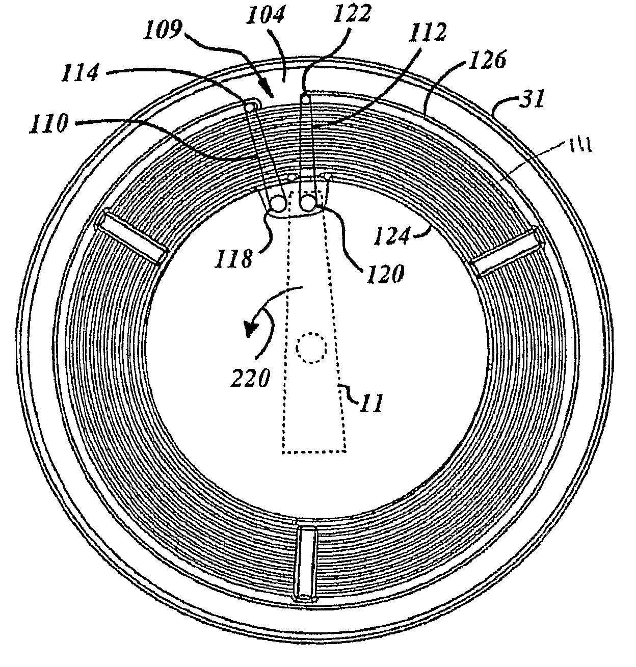
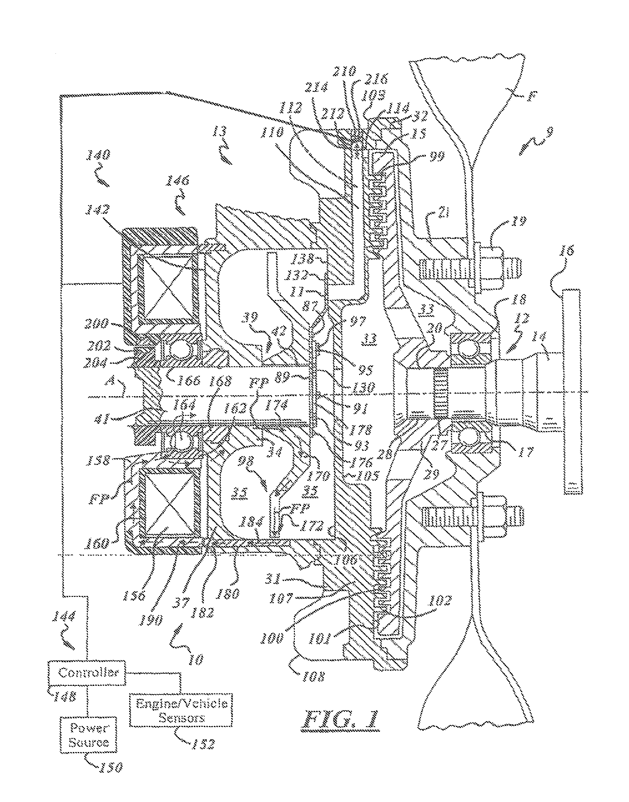
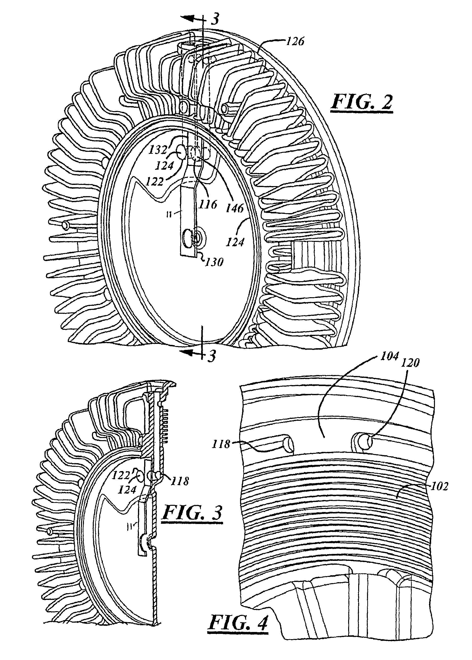
[0027]In the following figures the same reference numerals will be used to refer to the same components. Although the present invention may be used advantageously in clutch devices having various configurations and applications, it is especially advantageous in an electronically and / or mechanically controlled fluid-coupling device of the type used to drive a radiator cooling fan of an internal combustion engine. Although for simplicity the fluid-coupling device of the present invention will be described in connection with a cooling fan, it is to be understood that the invention is not limited to such uses and structures.

[0028]Also, a variety of other embodiments are contemplated having different combinations of the below described features of the present invention, having features other than those described herein, or even lacking one or more of those features. As such, it is understood that the invention can be carried out in various other suitable modes.

[0029]In the following desc...


PUM

PropertyMeasurementUnit
distanceaaaaaaaaaa
volumeaaaaaaaaaa
perimeteraaaaaaaaaa

Abstract

An engagement system (10) for a fluid-coupling device (9) may include a first engagement member (31) and a second engagement member (15) that is in operation with the first engagement member (31). A working chamber (33) is disposed between and at least partially defined by the first engagement member (31) and the second engagement member (15). The working chamber (33) has an inlet port (118) and an outlet port (120). A fluid reservoir (35) is fluidically-coupled to the working chamber (33). A scavenge valve (11) is coupled between the working chamber (33) and the fluid reservoir (35) and adjusts the fluid flow through the outlet port (120). An engagement system (10) for a fluid-coupling device (9) may in addition to or alternatively include a working chamber (33) that includes a working chamber inlet port (118) that is along an outer perimeter (126) of the first engagement member (31). A valve (11) is coupled between the working chamber (33) and the fluid reservoir (35) and adjusts the fluid flow through the working chamber.

Description

CROSS-REFERENCE TO RELATED APPLICATIONS[0001]This application claims the benefit of U.S. Provisional Application No. 60 / 806,804 filed in the United States Patent Office on Jul. 10, 2006.TECHNICAL FIELD[0002]The invention relates generally to fan drive systems. More specifically, the present invention relates to viscous fan drives and operational engagement and disengagement control techniques associated therewith.BACKGROUND ART[0003]The present invention relates to fluid-coupling devices of the type that include both a fluid operating chamber and a fluid reservoir chamber. The fluid-coupling devices often have valving, which controls the quantity of fluid entering and exiting the operating chambers thereof. The devices may be electronically or mechanically controlled.[0004]Although the present invention may be used advantageously in fluid-coupling devices having various configurations and applications, it is especially advantageous in a coupling device of the type used to drive a ra...

Claims


Application Information

Patent Timeline
Patent Type & Authority Patents(United States)
IPC IPC(8): F16D35/02
CPCF16D35/024F16D35/023Y10T137/0318F16D35/02F16D35/00F01P5/02
Inventor BOYER, RICK, L.
Owner BORGWARNER INC
Why Eureka
Try Eureka