Endoprosthesis assemblies and methods for using the same
What is Al technical title?
Al technical title is built by PatSnap Al team. It summarizes the technical point description of the patent document.
a technology of endoprosthesis and assembly, which is applied in the field of tissue support, can solve the problems of prone to such fatal problems and inadequate current evar devices and methods, and achieve the effect of minimizing and/or preventing the growth or rupture of aneurysms
Active Publication Date: 2014-04-22
CVDEVICES
View PDF14 Cites 0 Cited by
Summary
Abstract
Description
Claims
Application Information
AI Technical Summary
This helps you quickly interpret patents by identifying the three key elements:
Problems solved by technology
Method used
Benefits of technology
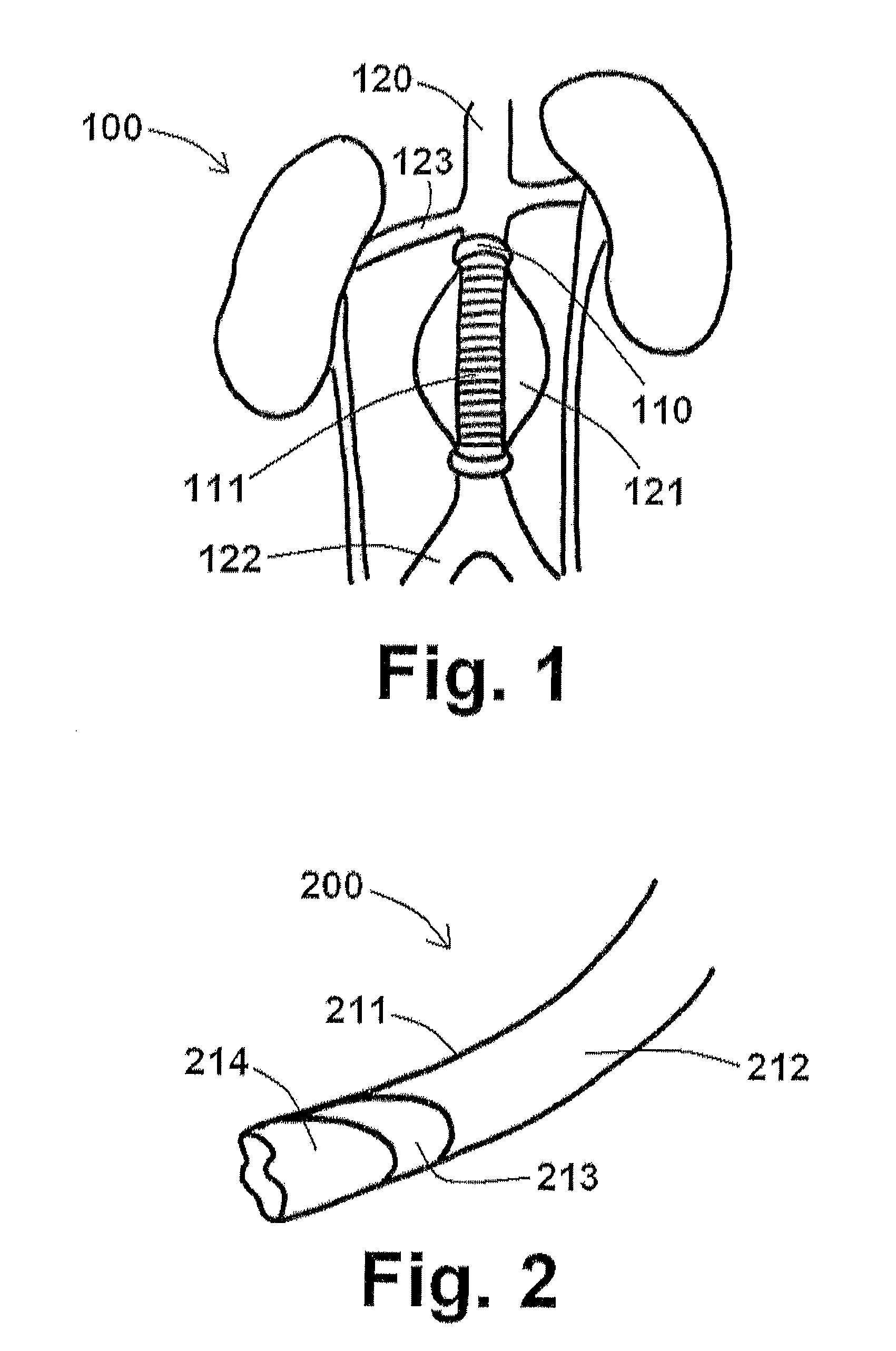
[0013]The current EVAR devices and methods are inadequate. They are prone to such fatal problems as migration, endoleak, and endotension. In order to address this medical problem, the present disclosure provides devices and methods for minimizing and / or preventing the growth or rupture of aneurysms or other vascular growth through the use of magnetic tissue support.
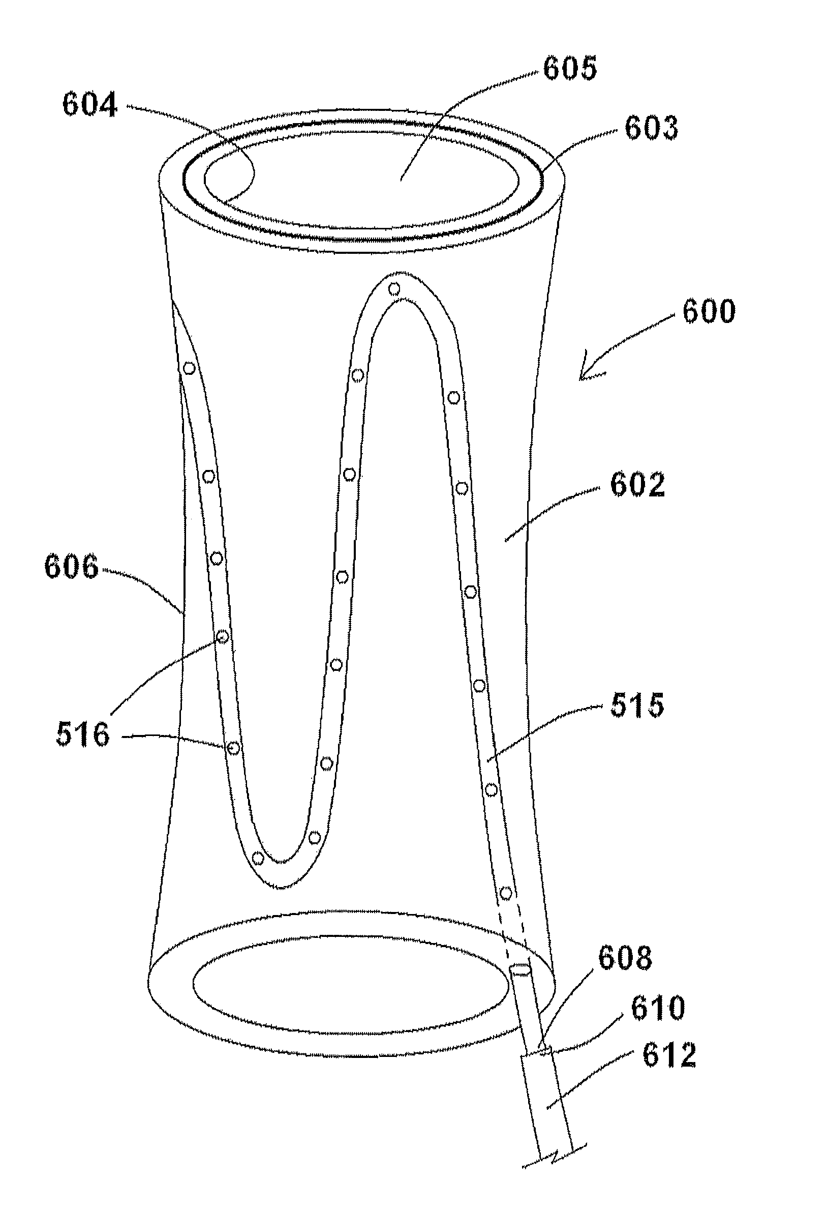
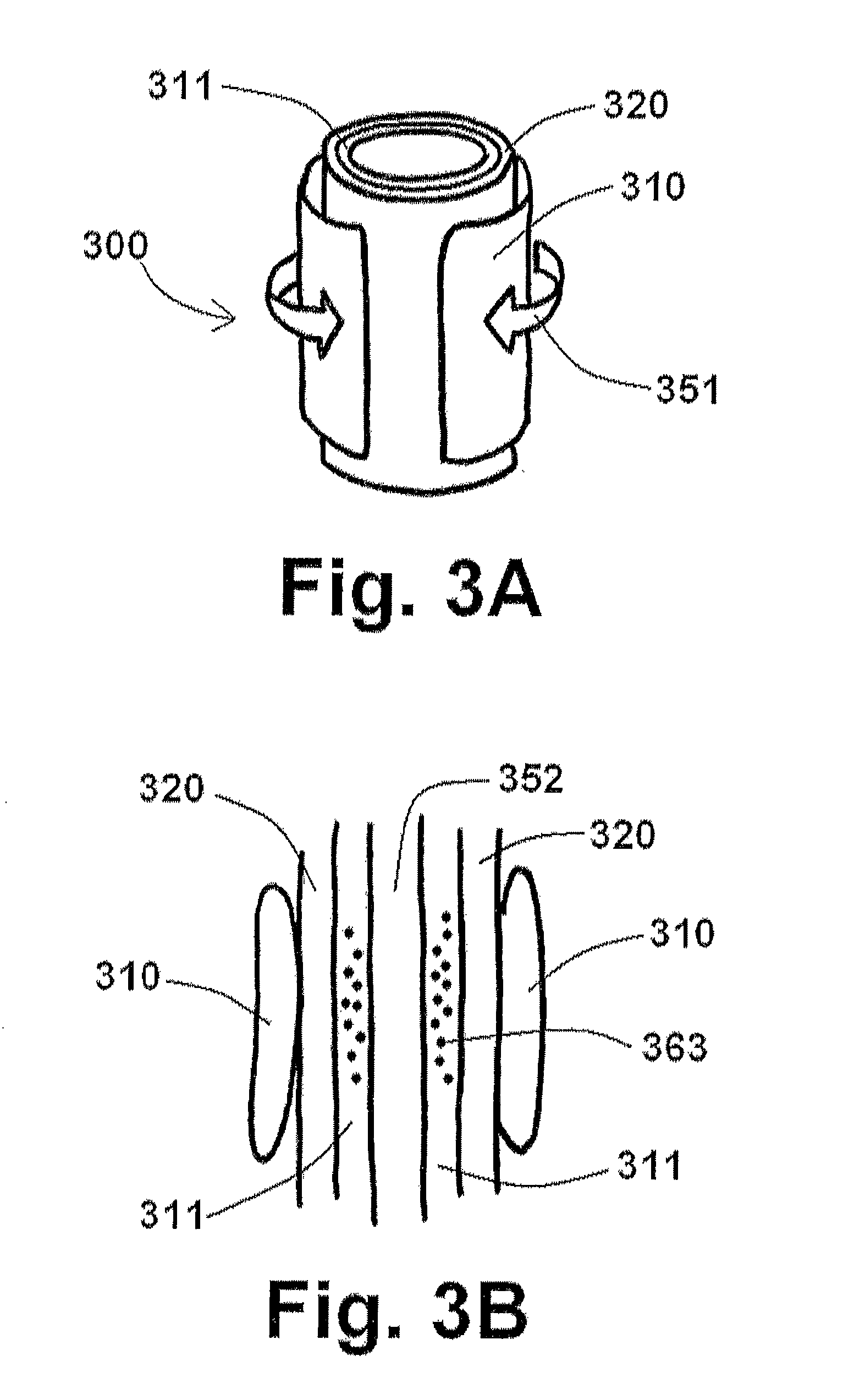
[0028]In at least one embodiment of an endoprosthesis assembly of the present disclosure, the endoprosthesis assembly comprises an endoprosthesis comprising an impermeable inner wall defining an endoprosthesis lumen sized and shaped to permit fluid to flow therethrough, a distal balloon positioned at or near a distal end of the endoprosthesis, the distal balloon capable of inflation to anchor the distal end of the endoprosthesis within a luminal organ, and a proximal balloon positioned at or near a proximal end of the endoprosthesis, the proximal balloon capable of inflation to anchor the proximal end of the endoprosthesis within the luminal organ, wherein when the endoprosthesis assembly is positioned within the luminal organ at or near an aneurysm sac, inflation of the distal balloon and the proximal balloon effectively isolates the aneurysm sac and prevents fluid within the aneurysm sac from flowing past the distal balloon and the proximal balloon and into other areas of vasculature adjacent to the aneurysm sac. In another embodiment, the endoprosthesis assembly further comprises a first tube defining one or more first tube openings, the first tube coupled to an outside of the inner wall of the endoprosthesis in a first configuration whereby the one or more first tube openings are exposed along the outside of the inner wall of the endoprosthesis.
[0035]In at least one embodiment of a method for using an endoprosthesis assembly, the step of operating a suction / infusion source to remove blood present within the aneurysm sac causes a wall of the vessel aneurysm to collapse toward the endoprosthesis assembly. In another embodiment, the step of operating a suction / infusion source to remove blood is performed along with a step of obtaining a first pressure measurement using a pressure sensor in communication with the aneurysm sac so to avoid negative pressure within the aneurysm sac, and wherein the step of operating a suction / infusion source to inject a substance is performed along with a step of obtaining a second pressure measurement using the pressure sensor so to avoid excessive pressure within the aneurysm sac. In an additional embodiment, the step of delivering an endoprosthesis assembly further comprises delivering a second endoprosthesis assembly within the vessel of the patient at or near the site of the vessel aneurysm sac of the vessel aneurysm, the second endoprosthesis assembly comprising a second endoprosthesis comprising a second impermeable inner wall defining a second endoprosthesis lumen sized and shaped to permit fluid to flow therethrough, a second distal balloon positioned at or near a second distal end of the second endoprosthesis, the second distal balloon capable of inflation to anchor the second distal end of the second endoprosthesis within a luminal organ, a second proximal balloon positioned at or near a second proximal end of the second endoprosthesis, the second proximal balloon capable of inflation to anchor the second proximal end of the second endoprosthesis within the luminal organ, and a second catheter having a second distal catheter end, a second proximal catheter end, and defining a second suction / infusion lumen therethrough and a second inflation / deflation lumen therethrough, wherein the second distal catheter end of the second catheter is configured to be removably coupled to the second endoprosthesis at or near the second proximal end of the second endoprosthesis, and wherein the step of operating the inflation / deflation source is performed to also inflate the second distal balloon and the second proximal balloon to isolate the aneurysm sac and prevent fluid within the aneurysm sac from flowing past the second distal balloon and the second proximal balloon and into other areas of vasculature adjacent to the aneurysm sac. In yet an additional embodiment, the step of delivering an endoprosthesis assembly is performed to position the proximal end of the endoprosthesis within a first luminal organ bifurcation of the luminal organ and to position the second proximal end of the second endoprosthesis within a second luminal organ bifurcation of the luminal organ.
Problems solved by technology
The current EVAR devices and methods are inadequate.
They are prone to such fatal problems as migration, endoleak, and endotension.
Method used
Image
Click on the blue label to locate the original text in one second.
Reading with bidirectional positioning of images and text.
Examples
Embodiment Construction
[0059]The disclosure of the present application provides various endograft and endoprosthesis devices and methods for using the same. For the purposes of promoting an understanding of the principles of the present disclosure, reference will now be made to the embodiments illustrated in the drawings, and specific language will be used to describe the same. It will nevertheless be understood that no limitation of the scope of this disclosure is thereby intended.
[0060]As discussed briefly above, the aneurysm size appears to be the one of the most important factors determining risk of aneurysm rupture. Changes in aneurysm dimension have been used as a surrogate marker for clinical efficacy after endovascular repair. Other morphological changes, including progressive angulation, and aortic neck enlargement, may occur in response to either aneurysm exclusion or associated degenerative changes in adjacent segments, respectively. In endovascular repair, the aneurysm sac is left intact and, ...
PUM
Abstract
Endoprosthesis assemblies and methods for using the same. In at least one embodiment of an endoprosthesis assembly of the present disclosure, the endoprosthesis assembly comprises an endoprosthesis comprising an impermeable inner wall defining an endoprosthesis lumen sized and shaped to permit fluid to flow therethrough, a distal balloon positioned at or near a distal end of the endoprosthesis, the distal balloon capable of inflation to anchor the distal end of the endoprosthesis within a luminal organ, and a proximal balloon positioned at or near a proximal end of the endoprosthesis, the proximal balloon capable of inflation to anchor the proximal end of the endoprosthesis within the luminal organ, wherein when the endoprosthesis assembly is positioned within the luminal organ at or near an aneurysm sac, inflation of the distal balloon and the proximal balloon effectively isolates the aneurysm sac and prevents fluid within the aneurysm sac from flowing past the distal balloon and the proximal balloon and into other areas of vasculature adjacent to the aneurysm sac.
Description
PRIORITY[0001]The present U.S. Continuation-in-part Patent Application is related to, and claims the priority benefit of, U.S. patent application Ser. No. 12 / 701,340, filed Feb. 5, 2010, which is related to, claims the priority benefit of, and is a continuation-in-part application of, U.S. patent application Ser. No. 11 / 997,147, filed Jun. 30, 2008 now U.S. Pat. No. 8,398,703, which is related to, claims the priority benefit of, an is a U.S. national stage entry of, International Patent Application Serial No. PCT / US2006 / 029424, filed Jul. 28, 2006, which is related to, and claims the priority benefit of, U.S. Provisional Patent Application Ser. No. 60 / 703,421, filed Jul. 29, 2005. The contents of each of these applications are hereby incorporated by reference in their entirety into this disclosure.BACKGROUND[0002]The present disclosure relates generally to tissue support, including devices and methods for aortic tissue support and for the treatment of aneurysms.[0003]Aortic aneurysm...
Claims
Application Information
Patent Timeline
Application Date:The date an application was filed.
Publication Date:The date a patent or application was officially published.
First Publication Date:The earliest publication date of a patent with the same application number.
Issue Date:Publication date of the patent grant document.
PCT Entry Date:The Entry date of PCT National Phase.
Estimated Expiry Date:The statutory expiry date of a patent right according to the Patent Law, and it is the longest term of protection that the patent right can achieve without the termination of the patent right due to other reasons(Term extension factor has been taken into account ).
Invalid Date:Actual expiry date is based on effective date or publication date of legal transaction data of invalid patent.