Imaging device and image analysis method

a technology which is applied in the field of image pickup and image analysis methods, can solve the problems of difficult to accurately analyze the movement of the ball, high risk of collision with the ball, and difficult to confirm the position of the moving ball at which the speed was measured

Active Publication Date: 2014-04-22
CASIO COMPUTER CO LTD
View PDF23 Cites 2 Cited by
  • Summary
  • Abstract
  • Description
  • Claims
  • Application Information

AI Technical Summary

Problems solved by technology

Therefore, such a speed-gun has to be placed along a movement direction of the ball and thus there is high risk of collision with the ball.
In addition, there is a problem that it is difficult to confirm at which position of the moving ball the speed was measured.
Thus it is difficult to analyze the ball movement accurately using a deformed image of the moving ball in the frame.

Method used


Image

  • Imaging device and image analysis method
  • Imaging device and image analysis method
  • Imaging device and image analysis method

Examples


first exemplary embodiment

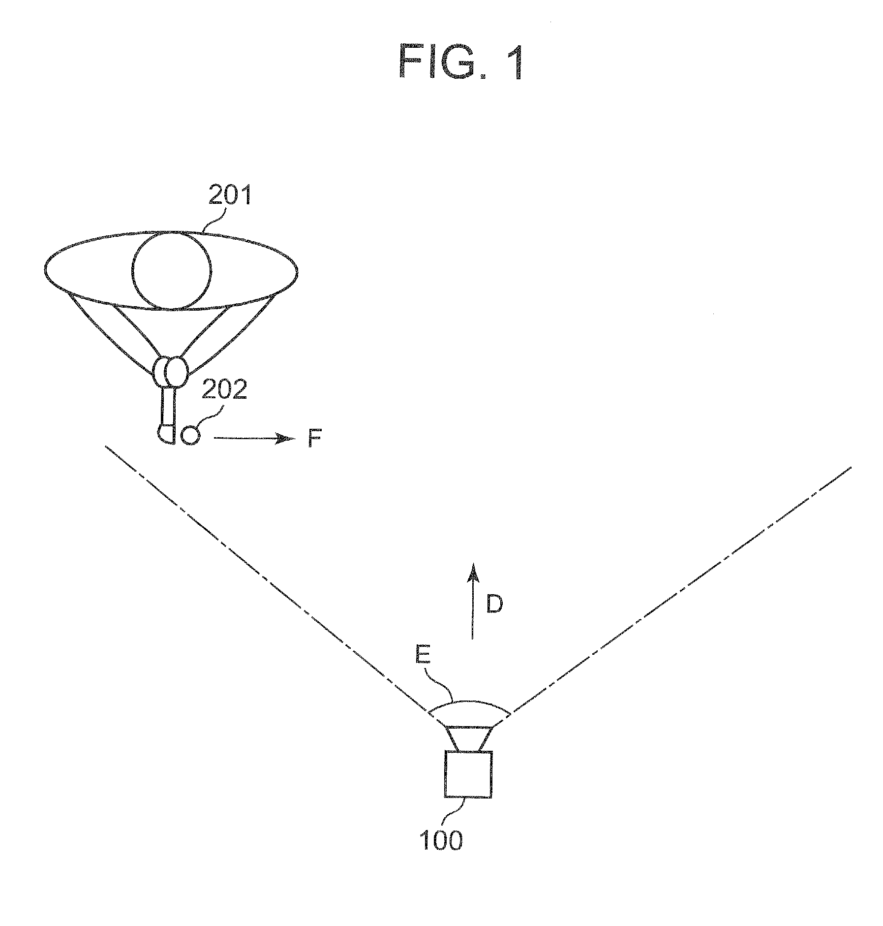
[0043]FIG. 1 is a plan view illustrating a usage state of an imaging device 100 according to an exemplary embodiment of the present invention. As shown in FIG. 1, the imaging device 100 is arranged such that an image pickup direction D is almost horizontal and a hitter 201 hits a round ball 202 to a direction F that is orthogonal to the image pickup direction D within an image pickup area E of the imaging device 100. It is arranged such that the ball 202 at the time of hitting is within the image pickup area E of the imaging device 100. The imaging device 100 captures continuous images such that the ball 202 is contained in each frame from the rest state before hitting to the moving state in high speed after hitting. The imaging device 100 analyzes a speed, hitting direction, rotating state, etc. of the ball 202 based on the frame images (also referred to as “frame” or “frames” simply hereinafter) in which the images of the ball 202 are captured continuously.

[0044]Preferably a color...

second exemplary embodiment

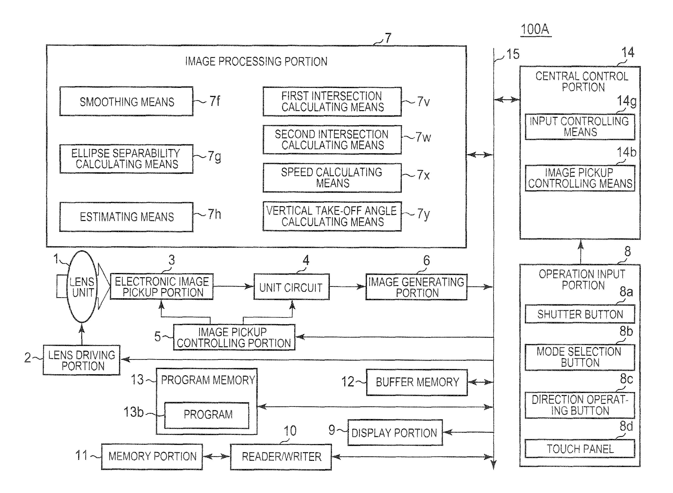
[0178]FIG. 27 is a schematic block diagram of an imaging device 100A according to a second exemplary embodiment of the present invention. Portions of the imaging device 100A of a second exemplary embodiment corresponding to those of the imaging device 100 of a first exemplary embodiment are designated by the same symbols.

[0179]The imaging device 100A differs from the imaging device 100 such that the program 13b stored in the program memory 13 is different from a program 13a and that the functions of the central control portion 14 and the image processing portion 7 are different because of the difference between the program 13a and the program 13b.

[0180]According to the imaging device 100A of a second exemplary embodiment, the program 13b makes the central control portion 14 function as an input controlling means 14g and an image pickup controlling means 14b. The image pickup controlling means 14b is the same as that of a first exemplary embodiment. The input controlling means 14g w...


PUM


Abstract

An imaging device includes a separability calculating portion for calculating a separability of a frame image by filtering the frame image containing a ball image elliptically deformed using an ellipse separability filter having an inside region and an outside region located outside of the inside region, an estimating portion for estimating a set of a center position, major axis, minor axis and inclination angle of the inside region, the set resulting in a maximum separability by changing the center position, major axis, minor axis and inclination angle of the inside region, as a set of a center position, major axis, minor axis and inclination angle of the ball image, and a speed calculating portion for calculating a speed of the ball based on a difference between the center positions of the ball images estimated by the estimating portion, a number of frames between the frame images and a frame rate.

Description

BACKGROUND OF THE INVENTION[0001]1. Field of the Invention[0002]The present invention relates to an imaging device (image pickup device) and an image analysis method that can analyze a movement of a ball from an image in a frame captured by an image pickup means using a rolling shutter system.[0003]2. Description of Related Art[0004]A speed-gun is well known as a device for measuring a speed of a ball used for a sport such as baseball, tennis, and the like.[0005]A speed-gun measures the Doppler effect of reflected waves from a ball, for example, and estimates a ball speed. Therefore, such a speed-gun has to be placed along a movement direction of the ball and thus there is high risk of collision with the ball. In addition, there is a problem that it is difficult to confirm at which position of the moving ball the speed was measured.[0006]For the purpose of avoiding such a collision with a ball, a method for measuring a speed of a moving ball by capturing an image of a ball from a di...

Claims


Application Information

Patent Timeline
Patent Type & Authority Patents(United States)
IPC IPC(8): G06T7/00G06T7/20H04N7/18
CPCG06T7/20G06T7/2033G06T2207/30241G06T2207/30204G06T7/60H04N5/3532G06T7/0097G06T2207/30221G06T2207/30224G06T7/246H04N25/531
Inventor NAKAGOME, KOUICHI
Owner CASIO COMPUTER CO LTD
Why Eureka
Try Eureka