
Hitch receiver apparatus for vehicle

a receiver and vehicle technology, applied in the direction of towed devices, vehicle components, bumpers, etc., can solve the problems of increasing weight and cost, reducing the height from the ground of the vehicle, and reducing the degree of freedom in vehicle design, so as to reduce the weight and cost. , the effect of improving the design freedom

Active Publication Date: 2014-05-13
HYUNDAI MOTOR CO LTD
View PDF25 Cites 8 Cited by
  • Summary
  • Abstract
  • Description
  • Claims
  • Application Information

AI Technical Summary

Benefits of technology

[0013]Various aspects of the present invention provide for a hitch receiver apparatus for a vehicle that is disposed such that a hitch receiver is not connected with a rear back beam, particularly, makes it possible to reduce the weight and cost by not using a separate hitch cover by making it possible to keep the hitch receiver in a rear back beam to perform the function of a rear back beam when the hitch receiver is not used, and makes it possible improve the degree of freedom in design of a vehicle.
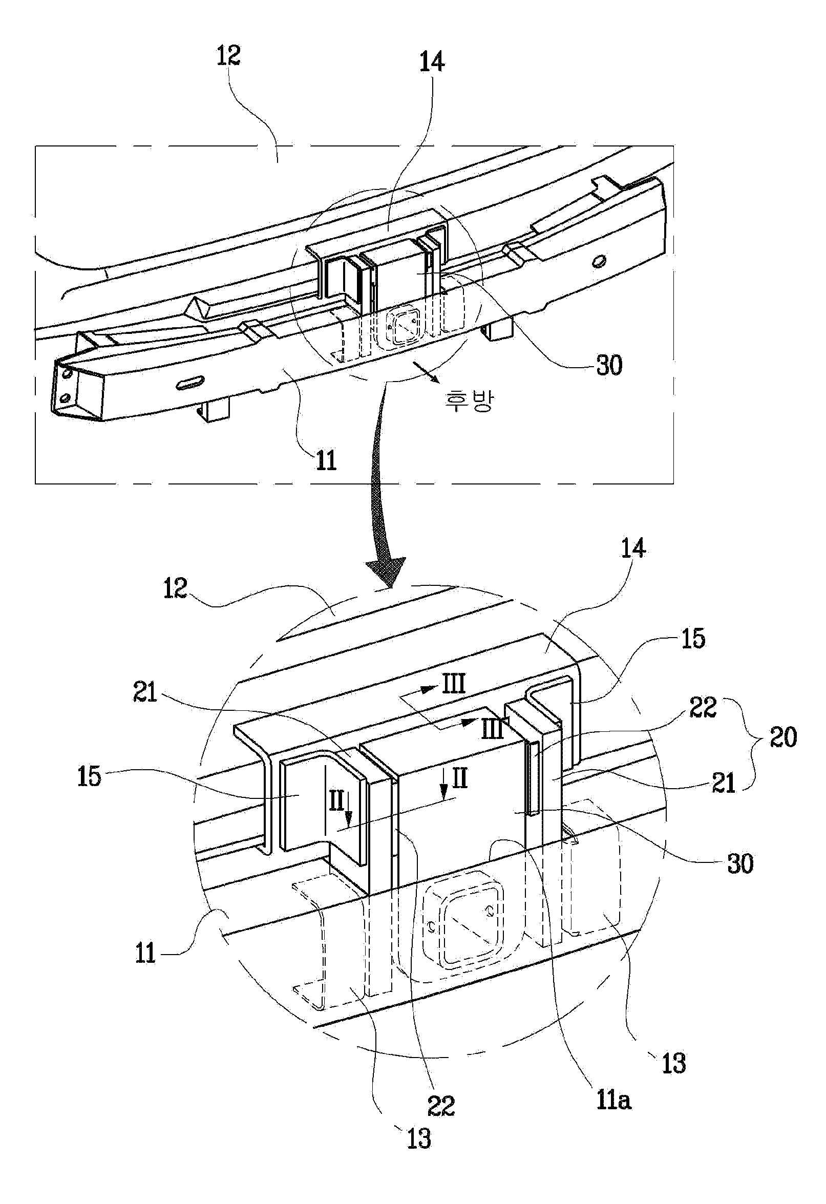
[0017]A back beam hole, through which the hitch guide and the hitch receiver pass, and the apparatus may further include a back beam reinforcing bracket integrally formed at the edge of the back beam hole to prevent reduction of rigidity of the rear back beam due to the back beam hole.
[0023]According to various aspects of the present invention, since it is possible to keep the hitch receiver in the rear back beam when not using the hitch receiver and to make the hitch receiver protrude down under the rear back beam when using as a trailer, it is not necessary to use a hitch cover, decrease the number of parts and reduce the weight and the cost, and increase the degree of freedom in design of a vehicle, such that it is also possible to improve the external esthetic appearance of the vehicle.

Problems solved by technology

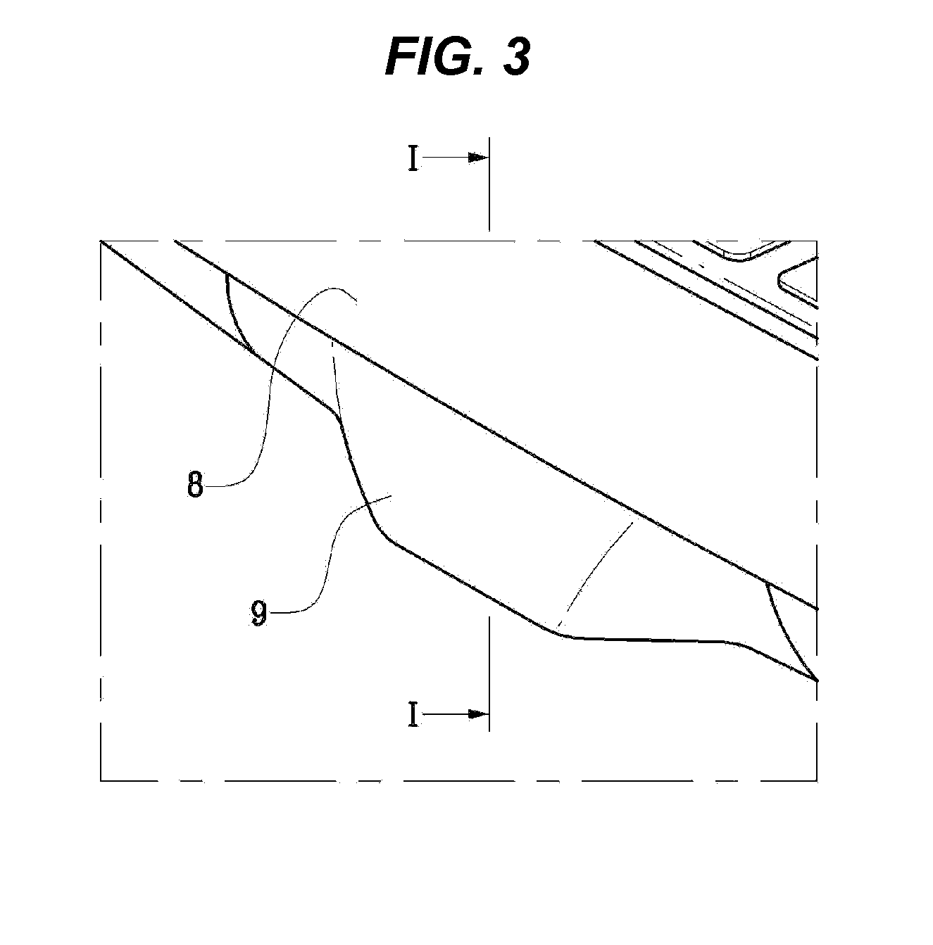
However, the hitch receiver apparatus having the configuration described above of the related art separately needs a hitch cover 9 covering the hitch receiver 1 other than a rear bumper 8 covering the rear back beam 3 because the hitch receiver 1 keeps protruding down under the rear back beam 3, as shown in FIGS. 3 and 4, even if the hitch receiver 1 does not function as a trailer, such that the weight increases and the cost increases.
Further, the height from the ground of a vehicle is decreased by the hitch cover 9, the hitch cover 9 is easily broken or damaged by frequent contact with the ground while the vehicle travels.
Further, when the reinforcing members 5 connected with the side member 4 are used to reinforce the strength of the hitch receiver 1, the weight and the cost increase.

Method used


Image

  • Hitch receiver apparatus for vehicle
  • Hitch receiver apparatus for vehicle
  • Hitch receiver apparatus for vehicle

Examples


Embodiment Construction

[0035]Reference will now be made in detail to various embodiments of the present invention(s), examples of which are illustrated in the accompanying drawings and described below. While the invention(s) will be described in conjunction with exemplary embodiments, it will be understood that present description is not intended to limit the invention(s) to those exemplary embodiments. On the contrary, the invention(s) is / are intended to cover not only the exemplary embodiments, but also various alternatives, modifications, equivalents and other embodiments, which may be included within the spirit and scope of the invention as defined by the appended claims.

[0036]A hitch receiver apparatus for a vehicle of the present invention includes, a shown in FIGS. 5 to 8, a hitch guide 20 connected with a car body frame 12 through a rear back beam 11 without being connected with the rear back beam 11 and a hitch receiver 30 connected with the hitch guide 20 to be able to move up / down along the hit...


PUM


Abstract

A hitch receiver apparatus for a vehicle is provided in which a hitch receiver is disposed without being directly connected with a rear back beam, such that the hitch receiver is kept in the rear back beam when not being used, and the hitch receiver protrudes down under the rear back beam when using the function of a trailer.

Description

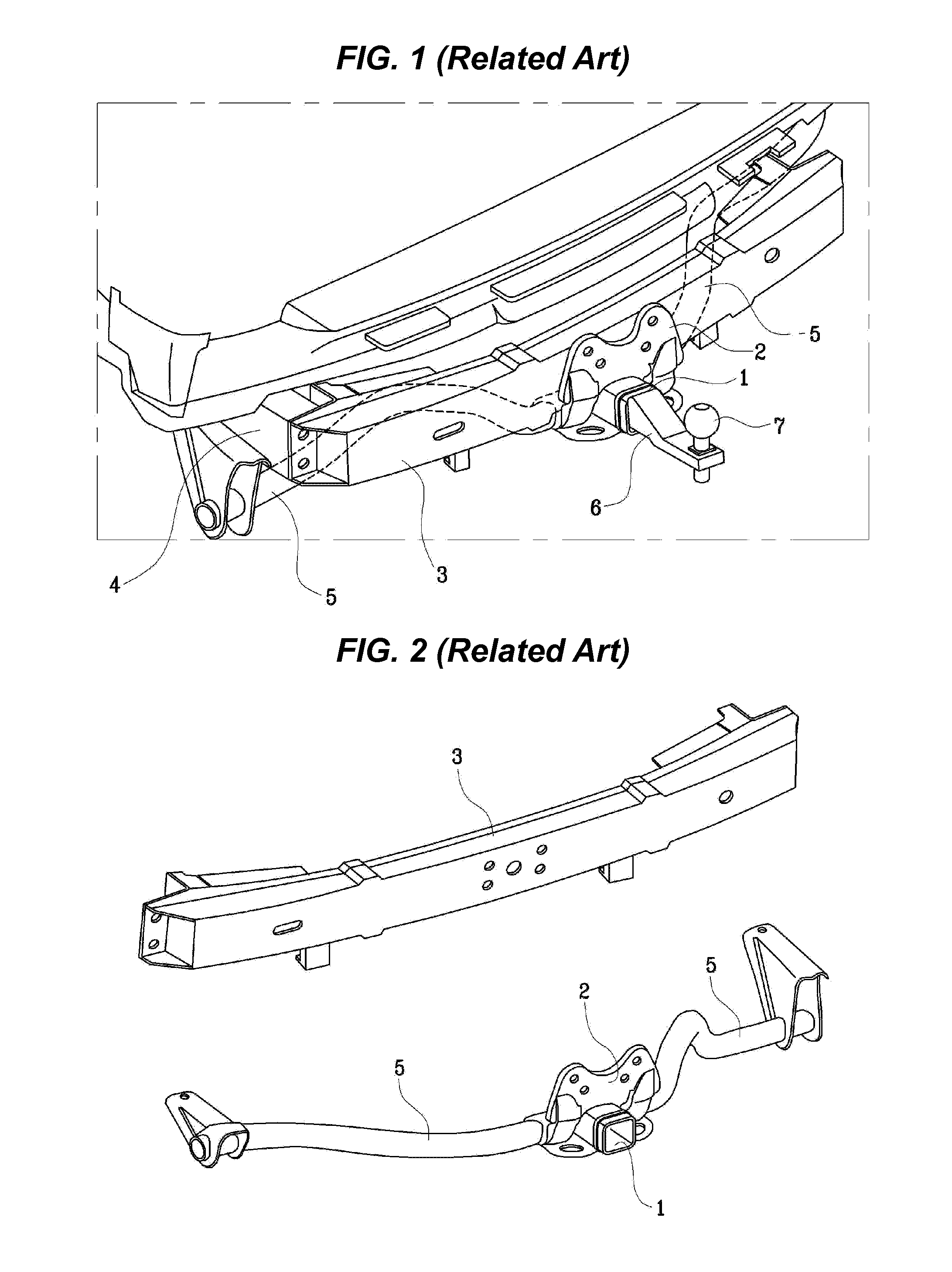
CROSS-REFERENCE TO RELATED APPLICATION[0001]The present application claims priority of Korean Patent Application Number 10-2011-0125679 filed Nov. 29, 2011, the entire contents of which application is incorporated herein for all purposes by this reference.BACKGROUND OF INVENTION[0002]1. Field of Invention[0003]The present invention relates to a hitch receiver apparatus. More particularly, it relates to a hitch receiver apparatus for a vehicle that is disposed not to be connected with a rear back beam.[0004]2. Description of Related Art[0005]In general, a hitch receiver apparatus performing the function of a trailer, as shown in FIGS. 1 and 2, has a structure in which a hitch receiver 2 and a receiver bracket 2 are integrally combined and the receiver bracket 2 is coupled to the center of a rear back beam 3, and if necessary, a plurality of reinforcing beams 5 connecting the receiver bracket 2 with the a side member 4 is additionally disposed.[0006]Further, when the function of a tra...

Claims


Application Information

Patent Timeline
Patent Type & Authority Patents(United States)
IPC IPC(8): B60D1/00
CPCB60D1/54B60D1/06B60D1/52B60D1/00B60R19/48
Inventor KIM, NAM CHEOLLEE, SEUNG MOKCHA, DONG EUNCHO, HOO TAEKLIM, KYOON SOO
Owner HYUNDAI MOTOR CO LTD
Learn More