[0010]Preferably, the base comprises an upper part and a lower part for engaging a floor surface, and wherein the oscillating means is arranged to oscillate the upper part of the base relative to the lower part of the base. The upper part of the base preferably houses said means for creating an air flow. This can further lower the centre of gravity of the fan assembly in comparison to prior art pedestal fans where a bladed fan and drive apparatus for the bladed fan are connected to the top of the pedestal and thereby rendering the fan assembly less prone to falling over if knocked.
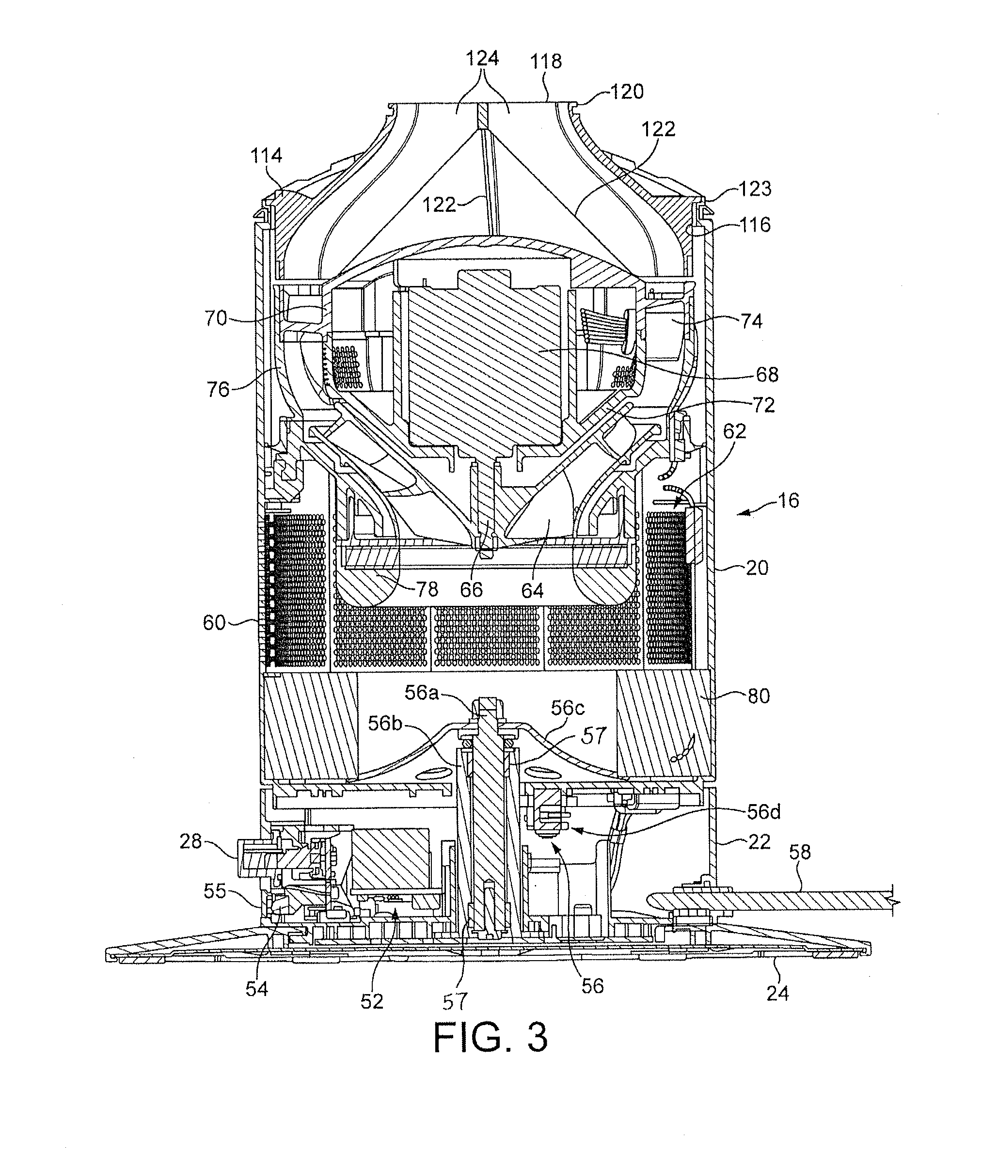
[0012]The stand preferably comprises, or is in the form of, a duct for conveying the air flow to the air outlet. Thus, the stand may serve to both support the air outlet through which an air flow created by the fan assembly is emitted and convey the created air flow to the nozzle. Preferably the means for creating an air flow through the nozzle comprises an impeller, a motor for rotating the impeller, and a diffuser located downstream from the impeller. The impeller is preferably a mixed flow impeller. The motor is preferably a DC brushless motor to avoid frictional losses and carbon debris from the brushes used in a traditional brushed motor. Reducing carbon debris and emissions is advantageous in a clean or pollutant sensitive environment such as a hospital or around those with allergies. While induction motors, which are generally used in pedestal fans, also have no brushes, a DC brushless motor can provide a much wider range of operating speeds than an induction motor.
[0013]The diffuser may comprise a plurality of spiral vanes, resulting in the emission of a spiraling air flow from the diffuser. As the air flow through the duct will generally be in an axial or longitudinal direction, the fan assembly preferably comprises means for guiding the air flow emitted from the diffuser into the duct. This can reduce conductance losses within the fan assembly. The air flow guiding means preferably comprises a plurality of curved vanes each for guiding a respective portion of the air flow emitted from the diffuser towards the duct. These vanes may be located on the internal surface of an air guiding member mounted over the diffuser, and are preferably substantially evenly spaced. The air flow guiding means may also comprise a plurality of radial vanes located at least partially within the duct, with each of the radial vanes adjoining a respective one of the curved vanes. These radial vanes may define a plurality of axial or longitudinal channels within the duct which each receive a respective portion of the air flow from channels defined by the curved vanes. These portions of the air flow preferably merge together within the duct.
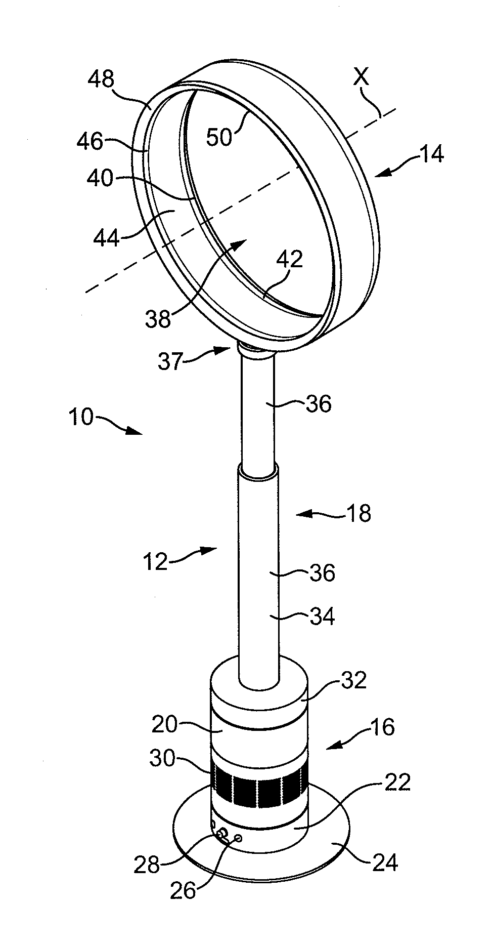
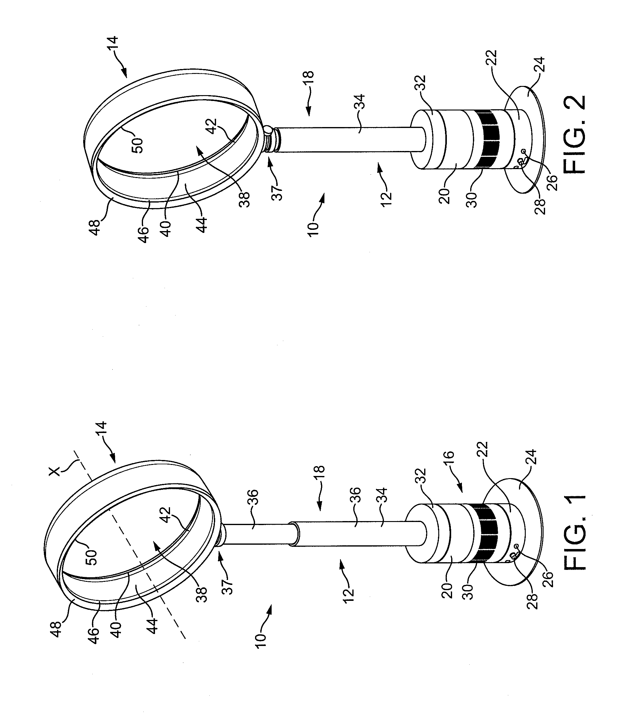
[0015]The fan assembly is preferably in the form of a bladeless fan assembly. Through use of a bladeless fan assembly an air current can be generated without the use of a bladed fan. In comparison to a bladed fan assembly, the bladeless fan assembly leads to a reduction in both moving parts and complexity. Furthermore, without the use of a bladed fan to project the air current from the fan assembly, a relatively uniform air current can be generated and guided into a room or towards a user. The air current can travel efficiently out from the nozzle, losing little energy and velocity to turbulence.
[0019]Preferably, the air outlet comprises a nozzle comprising an interior passage for receiving the air flow from the duct and a mouth for emitting the air flow. Preferably, the mouth of the nozzle extends about the opening, and is preferably annular. The nozzle preferably comprises an inner casing section and an outer casing section which define the mouth of the nozzle. Each section is preferably formed from a respective annular member, but each section may be provided by a plurality of members connected together or otherwise assembled to form that section. The outer casing section is preferably shaped so as to partially overlap the inner casing section. This can enable an outlet of the mouth to be defined between overlapping portions of the external surface of the inner casing section and the internal surface of the outer casing section of the nozzle. The outlet is preferably in the form of a slot, preferably having a width in the range from 0.5 to 5 mm, more preferably in the range from 0.5 to 1.5 mm. The nozzle may comprise a plurality of spacers for urging apart the overlapping portions of the inner casing section and the outer casing section of the nozzle. This can assist in maintaining a substantially uniform outlet width about the opening. The spacers are preferably evenly spaced along the outlet.

