Wheelchairs and Wheeled Vehicles Devices

Active Publication Date: 2009-07-02
SPINDLE MICHAEL J
View PDF41 Cites 19 Cited by
  • Summary
  • Abstract
  • Description
  • Claims
  • Application Information

AI Technical Summary

Benefits of technology

[0053]Preferably the grub screw is arranged so as to allow external access to the screws. This increases the ease of access to the screw should it become necessary for example, to adjust the screws. Providing external access allows the screw to be adjusted whilst the wheelchair is upright, without requiring dismantling of the castor wheel or the wheelchair.
[0054]The grub screw may be removable, so that the detent mechanism can be disabled if required. The ease of access to the screw also enables substitution of the spring for one of a higher rating if required. This provides a stronger resisting force on the casto

Problems solved by technology

Whilst satisfying many of the requirements of users, this arrangement of wheels is not ideally suited to anything other than smooth surfaces, since the front castors, which are limited by the layout to be small in diameter, have difficulty overcoming obstacles such as gravel, sand and small rocks encountered in off-road conditions.
In addition, in uphill as opposed to downhill conditions the weight distribution of the user about the chair is altered, which may lead to an unstable condition.
There is also a risk that conventional wheelchairs can tip backwards when the user pushes hard on the wheels in order to accelerate.
However, as the surfaces encountered by a wheelchair user, particularly off-road, are not likely to be smooth and level, a four-wheeled wheelchair of the front-drive design can find itself with only three of the wheels in contact with the ground and one wheel raised clear.
If one of these wheels is a driving wheel, the user may become immobilised, requiring assistance.
However, it has been found that existing three-wheeled wheelchairs are sometimes highly unstable, particular

Method used


Image

  • Wheelchairs and Wheeled Vehicles Devices
  • Wheelchairs and Wheeled Vehicles Devices
  • Wheelchairs and Wheeled Vehicles Devices

Examples


Embodiment Construction

[0076]The present embodiments represent the best ways known to the applicant of putting the invention into practice. However they are not the only ways in which this can be achieved.

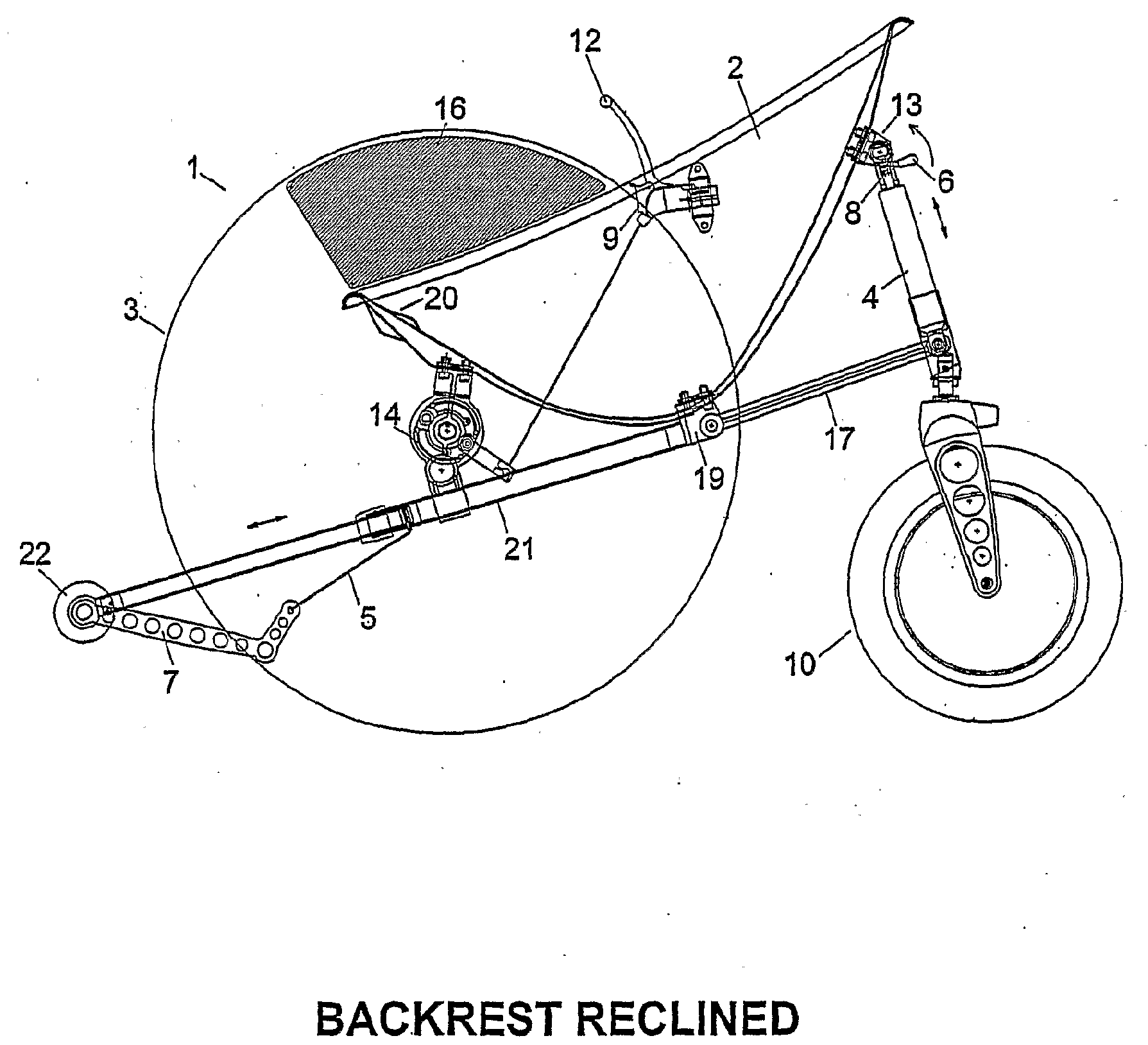
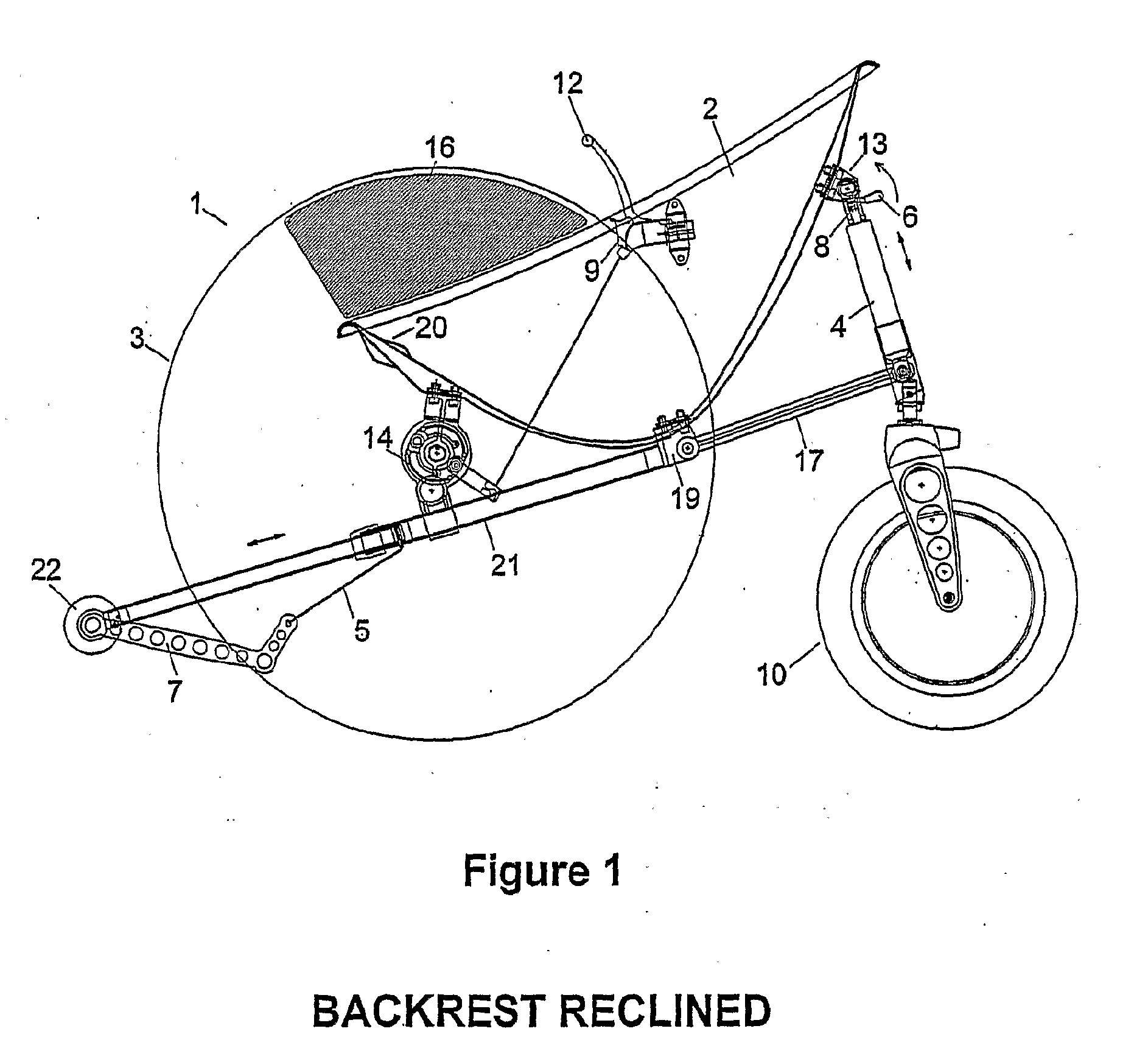
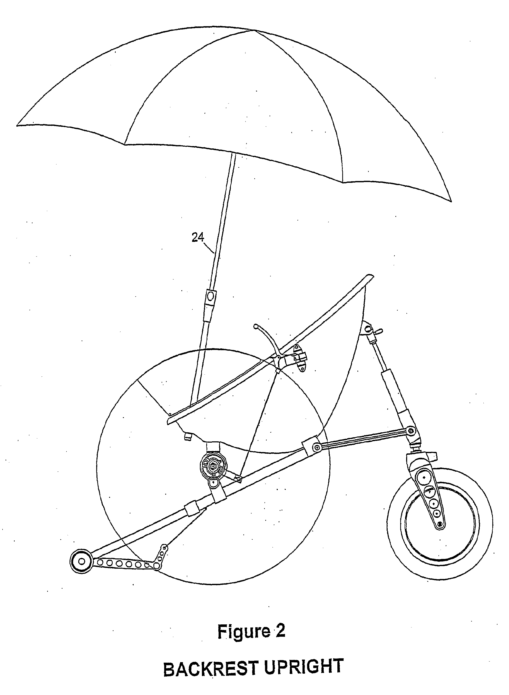
[0077]By way of an initial overview, the preferred embodiments provide a wheelchair or similar vehicle for personal use, comprising ground-engaging wheels and a user seat forming a structural member or monocoque on which the ground-engaging wheels are supported. The user seat may be of metal, plastics or composite material, e.g. fibre-reinforced plastics. If the seat is of plastics material, it may be in the form of a shell which may be moulded to fit the contours of the body of the user and may comprise a surrounding lip or rim to add stiffness to the structure. Alternatively or additionally, the seat may comprise stiffening ribs. The seat may comprise a single skin or may comprise inner and outer skins which may be separated and joined by a lightweight core, e.g. of rigid foam or of honeycomb material....


PUM


Abstract

A wheelchair comprising: three or more ground-engaging wheels; and a user seat, the user seat forming a structural member or monocoque on which the ground-engaging wheels are supported; wherein at least one of the wheels is connected to the seat by a support member, the length of the support member being adjustable during use. Also provided is a wheelchair or other wheeled vehicle, wherein at least one ground-engaging wheel is connected to a pivotable hub, and the said wheel is adjustable. Also provided is a wheelchair, wherein a ground-engaging wheel on each side of the wheelchair is provided with a brake. Also provided is a wheelchair or other wheeled vehicle in which one or more ground-engaging wheels are provided with ratchet means. A coupling arrangement for releasably joining two structural members is also provided. Also provided is a wheelchair including a rear castor with a detent mechanism.

Description

[0001]This invention relates to wheelchairs, and to other wheeled vehicles including, but not limited to, small personal vehicles of the nature of tricycles and the like.BACKGROUND TO THE INVENTION[0002]Many current wheelchairs have a well-known four wheel design, in which a pair of large rear wheels are propelled by the user and two smaller front castors facilitate maneuvering.[0003]Whilst satisfying many of the requirements of users, this arrangement of wheels is not ideally suited to anything other than smooth surfaces, since the front castors, which are limited by the layout to be small in diameter, have difficulty overcoming obstacles such as gravel, sand and small rocks encountered in off-road conditions. In addition, in uphill as opposed to downhill conditions the weight distribution of the user about the chair is altered, which may lead to an unstable condition. There is also a risk that conventional wheelchairs can tip backwards when the user pushes hard on the wheels in or...

Claims


Application Information

Patent Timeline
IPC IPC(8): A61G5/10A61G5/08A61G5/02B25G3/28B60T1/00
CPCA61G5/00Y10T403/7026A61G5/107A61G2005/0883A61G2005/0891A61G2005/1078A61G2005/1083A61G2005/1089A61G2005/1094A61G2005/1097A61G2005/128A61G2007/0528A61G5/1008A61G5/101A61G5/1024A61G5/1027A61G5/1035A61G5/02A61G5/0883A61G5/0891A61G5/1078A61G5/1083A61G5/1089A61G5/1094A61G5/1097A61G5/128A61G7/0528A61G5/1005A61G5/1086B62B5/0404B62D17/00F16C11/045A61G5/10
Inventor SPINDLE, MICHAEL J.
Owner SPINDLE MICHAEL J
Why Eureka
Try Eureka