
Portable remote controlled valve

a remote control and valve technology, applied in the field of firefighting equipment, can solve the problems of significant less battery power and less cost, and achieve the effects of less battery power, less bulky, and less cos

Active Publication Date: 2014-05-27
TASK FORCE TIPS
View PDF22 Cites 2 Cited by
  • Summary
  • Abstract
  • Description
  • Claims
  • Application Information

AI Technical Summary

Benefits of technology

The patent describes a new remote controlled valve that offers improved performance and reliability at a lower cost. The valve has a central chamber, an inlet, an outlet, and a valve mechanism to control the flow. Compared to previous devices, the new valve requires less battery power, is more portable, and can be easily operated remotely. Additionally, the valve can vent pressure to the atmosphere when closed. These technical improvements make the new valve a better solution for fire hose connections.

Problems solved by technology

However, the new valve requires significantly less battery power than comparable prior devices, and is thus can be made less bulky, less expensive, and more reliable.

Method used


Image

  • Portable remote controlled valve
  • Portable remote controlled valve
  • Portable remote controlled valve

Examples


Embodiment Construction

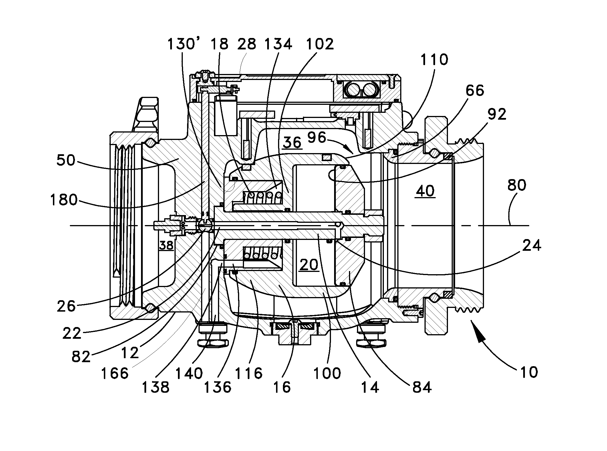
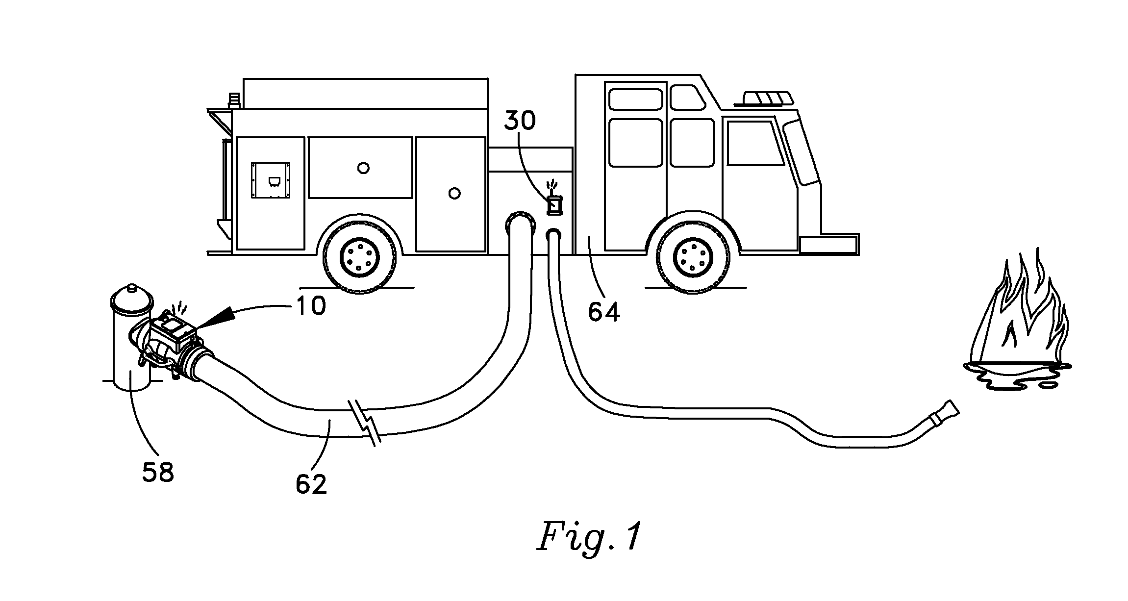
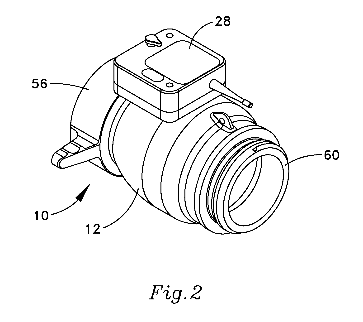
[0038]One possible example of a portable valve 10 that embodies the new invention can be seen in FIG. 1. As better seen in FIGS. 3B and 9-16, the valve has a main valve body 12, a valve shaft 14, a piston 16, and a spring 18. Each of these elements will be discussed in separate sections below. A pressure chamber 20 (best seen in FIGS. 3B, 12, 12A, and 14-16) is formed between the valve shaft and the piston, and is described in a separate section. A pilot channel 22, a pilot opening 24, and a pilot valve 26 (best seen in FIGS. 3B and 12A) are incorporated into the components, and will also be discussed in a separate section. The pilot valve is controlled by a pilot shaft 180 and electronics within an R / C housing 28, which will also be discussed. A remote controller 30 (seen in FIGS. 1, 17 and 18) will be discussed in a final section.

[0039]The Valve Body

[0040]The main valve body 12 has a central chamber 36, an inlet 38 to the central chamber, and an outlet 40 from the central chamber....


PUM


Abstract

A portable remote controlled fire-fighting valve has a central chamber in a main valve body, an inlet that connects to a hydrant, an outlet that connects to a fire hose, a valve mechanism that has a seating surface that seats against part of the device to open and close a flow channel through the central chamber, and a remote controller that enables an operator to selectively open and close the flow channel. The valve mechanism uses a piston that is mounted for axial movement within the central chamber. The piston has an annular wall that slides against an outer edge of a lateral chamber surface that is fixed in position within the main valve body. A spring biases the piston to the closed position. In the open position, water from the inlet flows around the piston, over its peripheral surface, to the outlet. A pressure chamber is formed between a lateral surface that is fixed in position within the valve body and a movable interior surface on the piston. A pilot channel extends from an upstream side of the flow channel to the pressure chamber. The remote controller selectively controls a pilot valve on the pilot channel, allowing liquid in the upstream side of the flow channel to flow to the pressure chamber and force the piston open.

Description

CROSS-REFERENCE TO RELATED APPLICATIONS[0001]Not applicable.BACKGROUND OF THE INVENTION[0002]The present invention relates generally to firefighting equipment and more particularly to a portable valve that can be attached to fire hydrants and operated remotely.[0003]In firefighting, fire hoses are usually connected to those fire hydrants nearest the fire, which are oftentimes hundreds of feet from the fire. A fireman removes a hose and hardware from the fire truck and places it at the hydrant. The firefighter then flushes the hydrant and attaches a valve and hose. When the hose is attached, the hydrant is opened; but it is not always known whether the valve itself will need to be opened. Opening the valve fills the hose with water, and commits the fire-fighters to a time-consuming and physically demanding process of draining the hose before it can be rolled and stored. This time commitment can be dangerous because the firefighters can be called to another site at any time, and added...

Claims


Application Information

Patent Timeline
Patent Type & Authority Patents(United States)
IPC IPC(8): F16K1/12
CPCF16K31/46A62C33/00F16K1/126Y10T137/3476
Inventor KOLACZ, DAVID J.MCMILLAN, STEWART G.AKINS, SCOTT W.MILLER, TIMOTHY S.
Owner TASK FORCE TIPS
Learn More