Portable remote controlled valve
a remote control and valve technology, applied in the field of firefighting equipment, can solve the problems of significant less battery power and less cost, and achieve the effects of less battery power, less bulky, and less cos
- Summary
- Abstract
- Description
- Claims
- Application Information
AI Technical Summary
Benefits of technology
Problems solved by technology
Method used
Image
Examples
Embodiment Construction
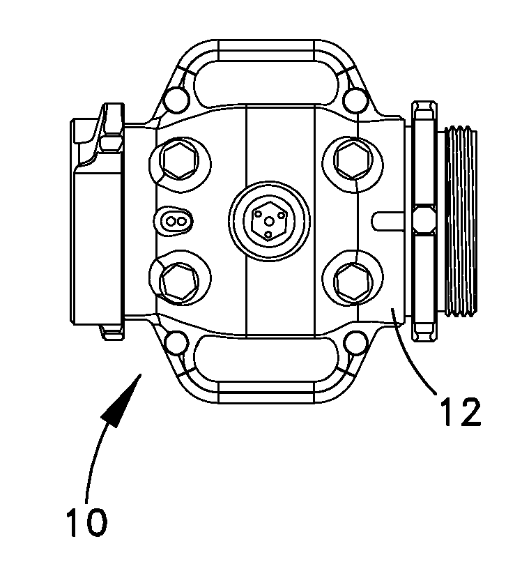
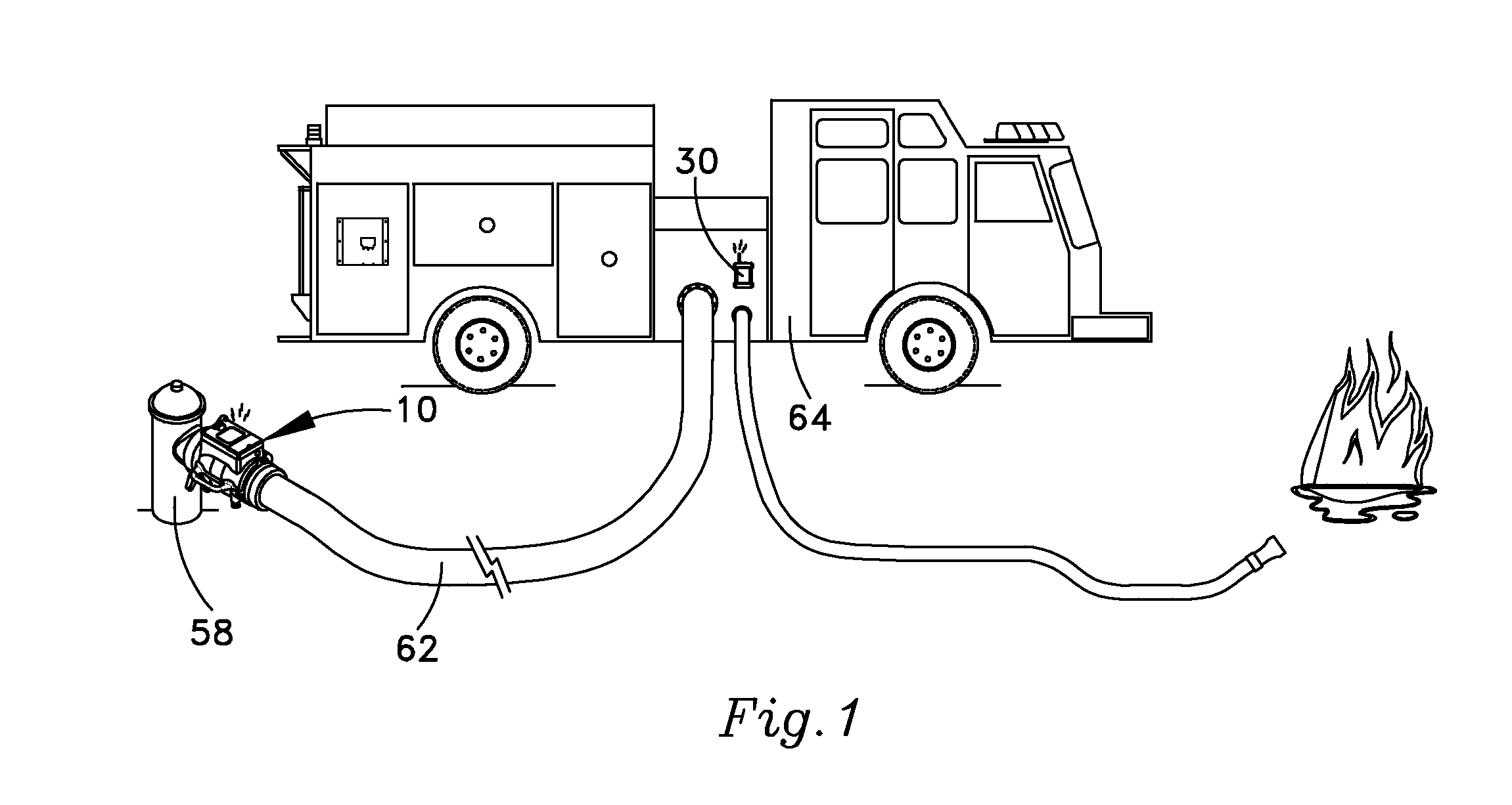
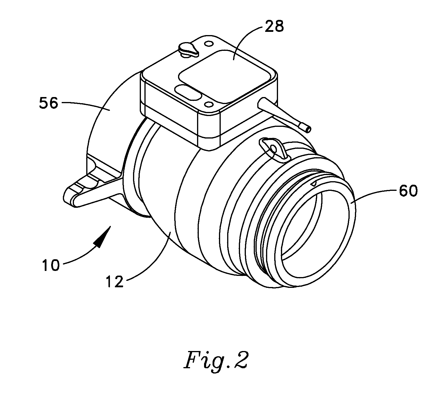
[0038]One possible example of a portable valve 10 that embodies the new invention can be seen in FIG. 1. As better seen in FIGS. 3B and 9-16, the valve has a main valve body 12, a valve shaft 14, a piston 16, and a spring 18. Each of these elements will be discussed in separate sections below. A pressure chamber 20 (best seen in FIGS. 3B, 12, 12A, and 14-16) is formed between the valve shaft and the piston, and is described in a separate section. A pilot channel 22, a pilot opening 24, and a pilot valve 26 (best seen in FIGS. 3B and 12A) are incorporated into the components, and will also be discussed in a separate section. The pilot valve is controlled by a pilot shaft 180 and electronics within an R / C housing 28, which will also be discussed. A remote controller 30 (seen in FIGS. 1, 17 and 18) will be discussed in a final section.
[0039]The Valve Body
[0040]The main valve body 12 has a central chamber 36, an inlet 38 to the central chamber, and an outlet 40 from the central chamber....
PUM
 Abstract
Description
Claims
Application Information
 - R&D
- Intellectual Property
- Life Sciences
- Materials
- Tech Scout
- Unparalleled Data Quality
- Higher Quality Content
- 60% Fewer Hallucinations
Browse by: Latest US Patents, China's latest patents, Technical Efficacy Thesaurus, Application Domain, Technology Topic, Popular Technical Reports.
© 2025 PatSnap. All rights reserved.Legal|Privacy policy|Modern Slavery Act Transparency Statement|Sitemap|About US| Contact US: help@patsnap.com


