
Method and device for determining the apical position in a dental root canal

a technology of apical position and root canal, applied in the field of apexlocating methods and devices, can solve the problems of not meeting the objective of dentists, based on second measuring principle, and not working on children

Active Publication Date: 2014-05-27
MAILLEFER INSTR HLDG
View PDF8 Cites 0 Cited by
  • Summary
  • Abstract
  • Description
  • Claims
  • Application Information

AI Technical Summary

Benefits of technology

The invention aims to develop a system, device, or method for accurately detecting the position of the apex of a tooth based on the absolute measurement of the depth of the apex. This means that the system should not require the setting of relative thresholds that are dependent on the patient or on changes in the root canal characteristics. The objective is to have a precise method for locating the apex, regardless of the root canal configuration or conditions.

Problems solved by technology

The first resistance measuring principle only makes it possible to detect when the apical terminus is passed, which does not satisfy the dentist's objective of being warned before having passed the apex.
A first disadvantage is that this second measuring principle, based on the detection of a drop in impedance at the cement / dentine junction of the apical constriction does not work on children and young patients because their teeth have little or no hypermineralised dentine.
In general, these two series of devices necessitate delicate rating and calibration operations, operations which are imprecise, tedious and a source of error.
In practice, and speaking generally, these two series of apex locators have the disadvantage of indicating the position of the apex only after the point of the electrode probe has crossed the apical constriction.
Another considerable problem is that the two measuring principles of these two series of apex locators have the disadvantage that the resistance / conductance measurements become wholly imprecise, even nonsensical, in the presence of conductive fluids in the root canal.
Such highly conductive ionic solutions totally disrupt conductivity measurements (resistance, impedance) and entirely invalidate any determination of the position of the apex.
The disadvantage of this device is that the fixing of the threshold value θ still necessitates calibration operations which are delicate, imprecise and a source of error.
For each individual canal of each root of each tooth it is necessary to recommence the rating and calibration operations, operations which are specialised, time-consuming and tedious for the dentist and which make these devices unattractive for the dentist to use.
Generally speaking, this third principle of detecting a difference in measurements made at two frequencies also has the disadvantage of not setting an absolute measuring criterion for the position of the apex.
The detection of the crossing of a threshold still has the disadvantage of being relative to the setting of an arbitrary threshold value.
This alternative measuring principle still has the disadvantage of not constituting an absolute criterion for determining the exact position of the apex but of referring to relative threshold values, varying according to the individuals concerned and the electrolytic conditions prevailing in each root canal, which means that the dentist has to perform calibration operations which are delicate, imprecise and a source of error.
The problem is that such measuring principles are directly affected by the presence of conductive fluids in the root canal which entirely invalidate the determination of the position of the apex.
Moreover, another general problem of the apex-locating devices based on measurements of impedance in the root canal of the tooth is that they do not permit resolution of complex teeth having several root canals or root canals with bifurcations or aberrations (multiple, forked, branched or twin roots, excrescences .

Method used


Image

  • Method and device for determining the apical position in a dental root canal
  • Method and device for determining the apical position in a dental root canal
  • Method and device for determining the apical position in a dental root canal

Examples


Embodiment Construction

[0100]In the present invention a conductive endodontic probe is used which may have various forms and in particular be formed by a metal rod, point or file which acts as an electrode. The probe electrode is preferably in the form of a narrow, elongate, flexible metal rod, of centimetric length (of the order of one centimeter or a fraction of a centimeter to several centimeters, not more than a decimeter, typically 2-3 cm). This rod or file with a round or other cross-sectional shape has a diameter (transverse dimension) clearly less than its length. The metal rod which acts as a terminal electrode (in electrical contact with an intermediate connection electrode and / or connected to an output terminal of the generator GF) can be covered over all or part of its length by an insulating covering as in the plots of experimental curves as reported hereinafter in relation to FIGS. 11A and 11B. It is possible, in particular, to use endodontic probes which are available through commercial net...


PUM


Abstract

An apex-locating method and device for determining the depth position of the apex in a dental root canal. It uses a device making it possible to form a circuit including a first probe electrode inserted into the root canal of a tooth, a second electrode in conductive contact with an oral mucous membrane, frequency-generating elements able to produce alternating electrical signals at a number of frequencies, and elements for measuring electrical magnitude of alternating signals in the circuit. Provision is made for exciting the circuit and measuring the levels of magnitude of the alternating signals, respectively at low frequency and at high frequency and for detecting a point of intersection where the two levels measured at low and high frequencies meet and become substantially equal, these frequencies being sufficiently far apart for this point of intersection to exist. This point gives the position of the apex.

Description

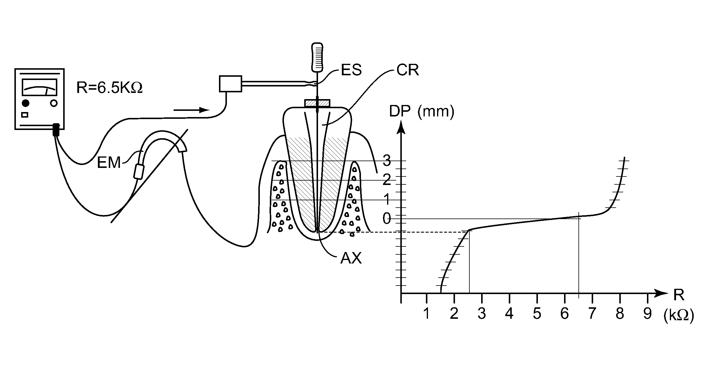
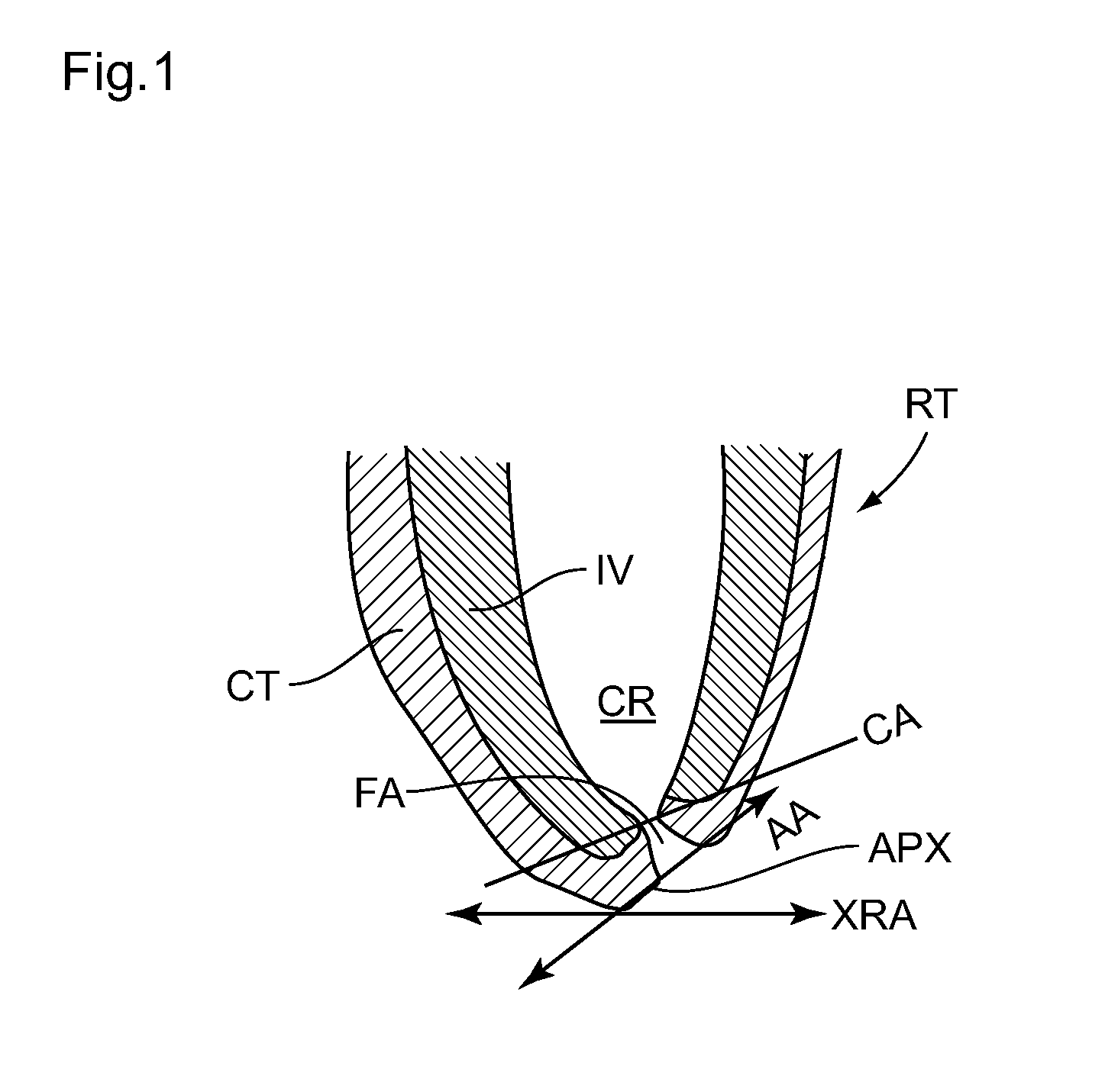
BACKGROUND OF THE INVENTION[0001]1. Field of the Invention[0002]The present invention relates to the area of apex-locating methods and devices which are used in endodontics to locate, in a root canal of a tooth, the position of the apex in terms of depth, i.e. the position of the summit of this root (i.e. apical terminus) and, more precisely, the end of the orifice of the apical foramen at the bottom of the root canal.[0003]2. Description of the Related Art[0004]During dental surgery procedures, in particular during a procedure to clean and shape the root canal, the apex locators serve to avoid crossing the apical foramen, i.e. passing the apical terminus and to keep the subjacent maxillary ligament with its nerve bundles from being reached.[0005]FIG. 1 shows the anatomical structure of a tooth in a schematic view along a plane of cut along the axis of the canal of a root of the tooth. Certain teeth, such as the molars and premolars, can have a number of roots RT or at least several...

Claims


Application Information

Patent Timeline
Patent Type & Authority Patents(United States)
IPC IPC(8): A61C19/04
CPCA61C19/041A61B5/0534A61B5/063A61C19/042A61B5/4547
Inventor AEBY, FRANCOISFARINE, PIERRE-ANDREMERZ, ROMANBOTTERON, CYRIL
Owner MAILLEFER INSTR HLDG
Learn More