Method for attaching a supporting bearing in a steering rack housing for a power steering system

a technology for steering racks and supporting bearings, which is applied in the direction of electrically conductive connections, non-disconnectible pipe joints, ropes and cables for vehicles/pulleys, etc., can solve the problems of relatively large labor and high cost of manufacturing the constricted portion, and achieve the effect of reducing labor and cos

Active Publication Date: 2014-06-10
KNORR BREMSE SYST FUER NUTZFAHRZEUGE GMBH
View PDF17 Cites 1 Cited by
  • Summary
  • Abstract
  • Description
  • Claims
  • Application Information

AI Technical Summary

Benefits of technology

[0009]It is the object of the invention to reduce the production effort and the costs for a steering rack housing and still meet the demands with regard to quality and grades.
[0011]Production of such a steering rack housing and the fastening of the supporting bearing within the steering rack housing are quick and simple to carry out. It is not necessary, according to the invention, to peripherally reduce the diameter of the entire steering rack housing; two cross-sectional contractions which are, if possible, diametrically opposed are sufficient. For this purpose, the supporting bearing, during attachment within the steering rack housing, is first brought to its functional position, then the cross section of the steering rack housing is changed from the outside with a corresponding tool. In a particularly advantageous process, it is sufficient, for example, to produce two punched-in portions from the outside. However, in order to further improve the attachment, three or more cross-sectional contractions uniformly distributed over the outer circumference of the steering rack housing can also be incorporated.
[0015]A “stop” within the sense of the invention is to be construed broadly. For example, the stop can cooperate directly with the steering rack, for example with a thickened portion provided thereon, and limit its displacement in one direction. Preferably, the stop is designed in such a way that during the displacement of the steering rack during steering, a joint part of the joint, for example ball joint, connecting the steering rack with the track rod contacts the stop in order thus to limit the displacement of the steering rack.
[0016]A preferred embodiment of the steering rack housing according to the invention is characterized in that the stop is provided by a stop part inserted into the passage and produced from steel sheet, or that the stop is formed on the steering rack housing. Advantageously, a conventional stop ring can thus be omitted. This saves weight and reduces not only the transport costs of the rack-and-pinion steering system, but also reduces the weight of the vehicle concerned and thus improves its energy balance. In addition, the production of the stop part with steel sheet or forming the stop on the housing is comparatively simple and can take place with few working steps, which reduces production costs. Moreover, the stop part produced from steel sheet can be connected to the housing with comparative ease by resistance welding, which reduces thermal stresses and thus the danger of deformation. The stop or stop part are not limited to the stopping function and can also additionally serve for supporting and guiding the steering rack.
[0018]In a particularly simple variation of the stop formed by the steering rack housing, the stop is formed by the passage, or its cross section, being so narrowly dimensioned over the entire length of the passage that a stop of the steering rack or the joint between the steering rack and the track rod occurs at the edge of the passage. In this embodiment, the steering rack housing advantageously does not require any further processing in order to produce the stop.
[0019]In another advantageous embodiment, the stop or the stop part is defined by a cross-sectional reduction of the passage of the steering rack housing which is symmetrical to the longitudinal axis of the passage. The stop can thus be provided with certainty, and above all, without the necessity of having to pay attention to an assembly direction during assembly.

Problems solved by technology

The fabrication of the constricted portion entails relatively large efforts and correspondingly high costs.

Method used


Image

  • Method for attaching a supporting bearing in a steering rack housing for a power steering system
  • Method for attaching a supporting bearing in a steering rack housing for a power steering system
  • Method for attaching a supporting bearing in a steering rack housing for a power steering system

Examples


Embodiment Construction

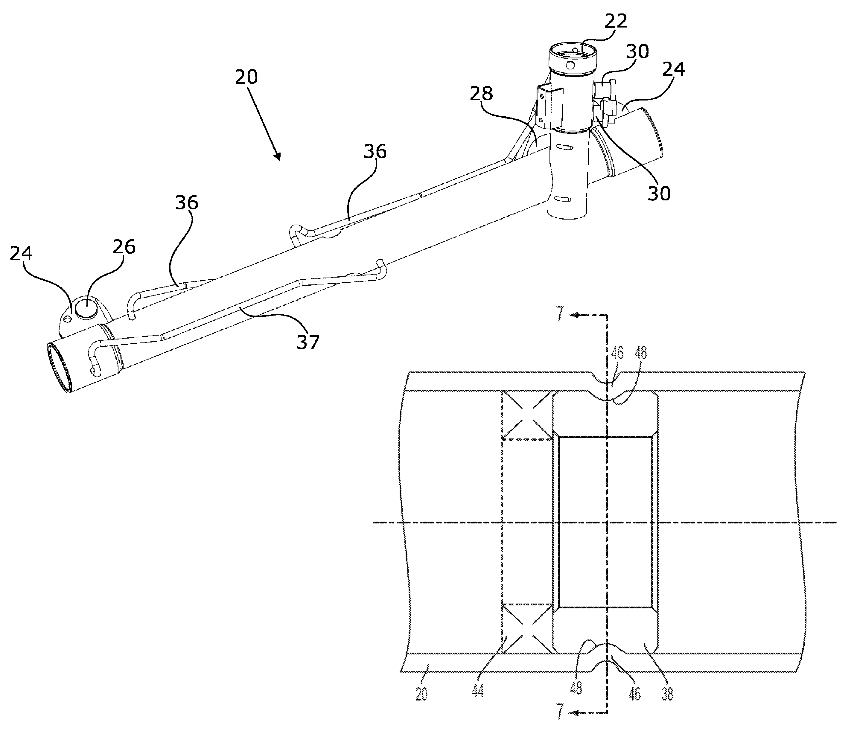
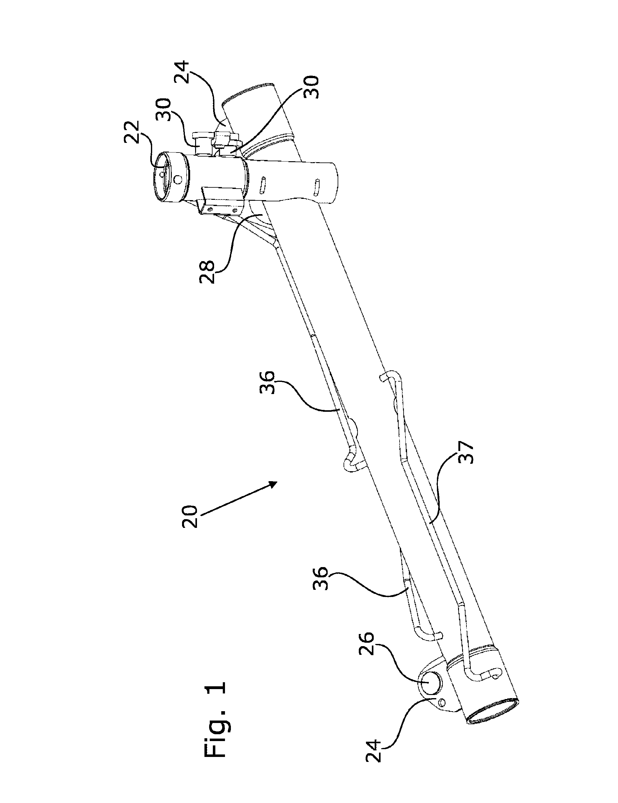
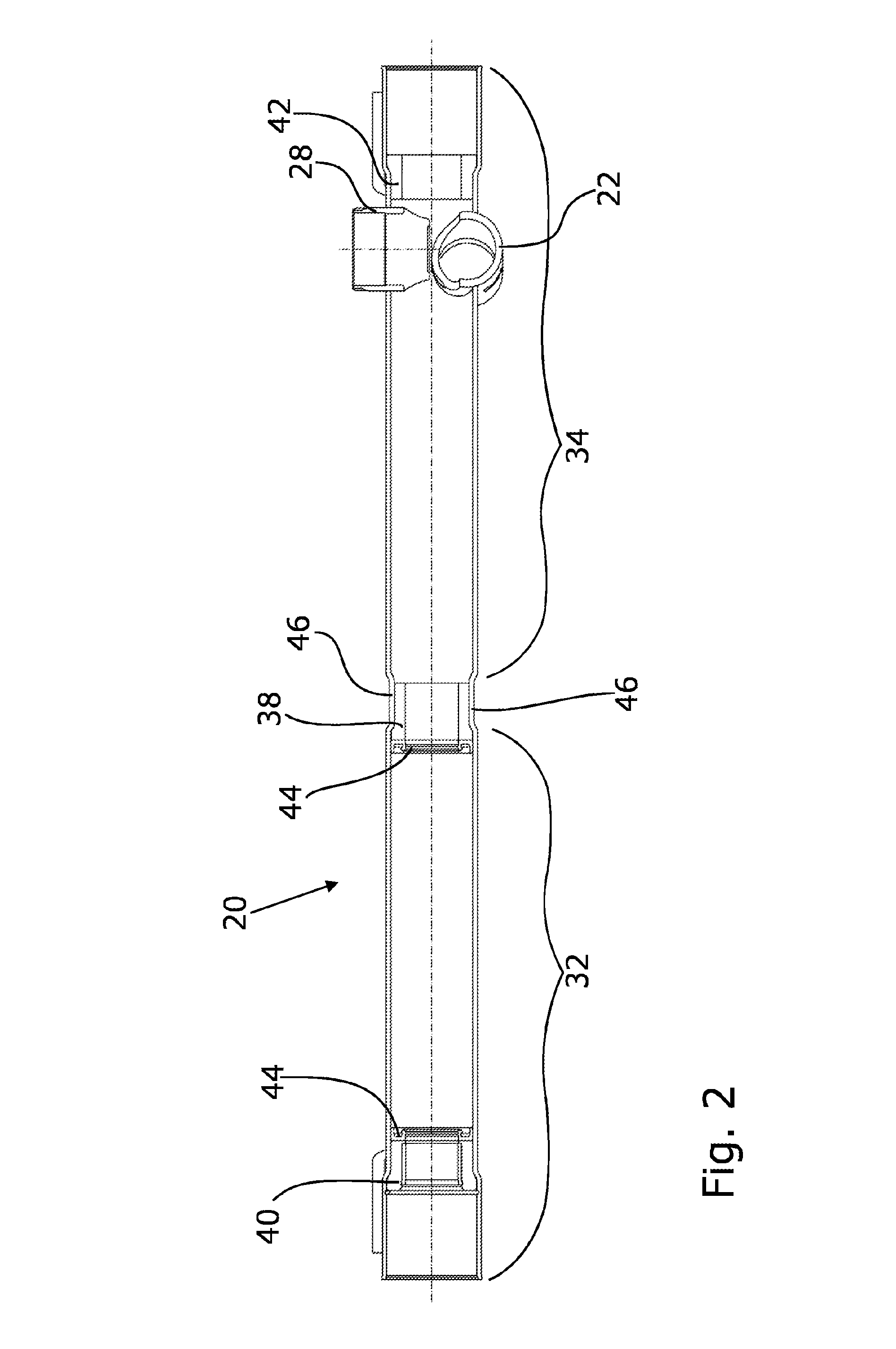
[0034]A steering rack housing 20 according to the invention is configured to be substantially cylindrical. A steering rack, which is not shown, is located within the steering rack housing 20. The steering rack is moved via a pinion connected to the steering column. This pinion, which is also not shown, is disposed in a tower pipe 22. To this end, both the steering rack housing 20 as well as the tower pipe 22 comprise openings which in the mounted state are aligned and form a pinion engagement region.

[0035]FIG. 1 further shows that the steering rack housing 20 has brackets 24 for attachment, which are respectively substantially disposed at the end and which comprise attachment openings 26.

[0036]On the side of the steering rack housing 20 opposite from the tower pipe 22, a sliding member tower 28 is disposed in which a sliding member, which is also not visible, is accommodated. In the exemplary embodiment shown, the tower pipe 22 comprises two supply sockets 30.

[0037]The tower pipe is...


PUM

PropertyMeasurementUnit
forceaaaaaaaaaa
circumferenceaaaaaaaaaa
resilienceaaaaaaaaaa

Abstract

A steering rack housing (20, 100, 100′, 100″) for a power steering system that surrounds a steering rack in a tubular manner and includes a hydraulic region (32), a mechanical region (34), and as an inner supporting bearing (38), wherein the supporting bearing is held in the steering rack housing (20, 100, 100′, 100″) by at least two cross-sectional contractions (46) of the housing.

Description

[0001]This nonprovisional application is a continuation-in-part of U.S. Ser. No. 13 / 242,119 filed Sep. 23, 2011, now abandoned, in the U.S. Patent and Trademark Office and claims the benefit of commonly assigned International Application No. PCT / EP2010 / 053711, which was filed on Mar. 22, 2010, pending, which designates the U.S., and claims priority to German Patent Application No. DE 10 2009 001 805.0, which was filed in Germany on Mar. 24, 2009, and which are all herein incorporated by reference.BACKGROUND OF THE INVENTION[0002]The invention relates to a steering rack housing for a power steering system which surrounds a steering rack in a tubular manner and comprises at least a hydraulic region and a mechanical region as well as an inner supporting bearing.[0003]Rack-and-pinion steering systems are used in motor vehicles for converting the rotating steering movement applied through the steering wheel into a rectilinear movement for pivoting the vehicle wheels to be steered. In thi...

Claims


Application Information

Patent Timeline
Patent Type & Authority Patents(United States)
IPC IPC(8): B21D53/88B23P21/00F16L13/14B23P11/00B23P9/00B21D17/00
CPCF16H57/023F16H57/021F16H2057/0216F16H2057/02082B62D5/22Y10T29/49908Y10T29/49835Y10T29/49696Y10T29/49837Y10T29/49913Y10T29/49833Y10T29/49861Y10T29/49917Y10T29/49826Y10T74/2186Y10T29/49904Y10T403/4991Y10T29/49909Y10T29/49622
Inventor HEIN, PAULKOGAN, ALEXANDERKELLER, JENS
Owner KNORR BREMSE SYST FUER NUTZFAHRZEUGE GMBH
Why Eureka
Try Eureka