Elevator system including monitoring arrangement to activate emergency braking procedure based on deceleration and method of operating the same

a technology of emergency braking and elevator, which is applied in the direction of control systems, elevators, electric motor speed/torque regulation, etc., can solve the problems of long end buffers, limited collision damping capability, and a rather unpleasant gripping experien

Active Publication Date: 2014-06-17
KONE CORP
View PDF18 Cites 13 Cited by
  • Summary
  • Abstract
  • Description
  • Claims
  • Application Information

AI Technical Summary

Benefits of technology

[0005]The aim of the invention is therefore to disclose a method for monitoring the movement of an elevator car, and also an elevator system wherein the movement of an elevator car is monitored. According to the invention, the deceleration of the elevator car is increased progressively in connection with an emergency stop of the elevator car by activating separate emergency braking procedures consecutively such that it is endeavored to stop the elevator car with as small a deceleration as possible while, however, simultaneously taking into account the safety of the elevator passengers.

Problems solved by technology

When using shallow end zones also the length of the end buffers, and therefore the collision damping capability, is usually limited.
A passenger in the elevator may find the gripping situation a quite unpleasant experience owing to the significantly greater than normal deceleration of the elevator car during the gripping.
When the elevator is driving upwards, if the deceleration of the elevator car were to exceed the acceleration of free fall of the attractive force of the earth's gravity when the elevator is driving upwards, there would be the additional danger that an elevator passenger would rise into the air as a consequence of the gripping situation.
Additionally, during an emergency stop of the elevator car the deceleration might vary in different parts of the elevator hoistway owing to, among other things, the effect of the weight of the elevator ropes.
Elongation of the elevator ropes, on the other hand, might result in the speed of the elevator car during deceleration being momentarily greater than that permitted even if the speed of the traction sheave of the hoisting machine were to decelerate in the manner specified by the speed reference.

Method used


Image

  • Elevator system including monitoring arrangement to activate emergency braking procedure based on deceleration and method of operating the same
  • Elevator system including monitoring arrangement to activate emergency braking procedure based on deceleration and method of operating the same
  • Elevator system including monitoring arrangement to activate emergency braking procedure based on deceleration and method of operating the same

Examples


embodiment 1

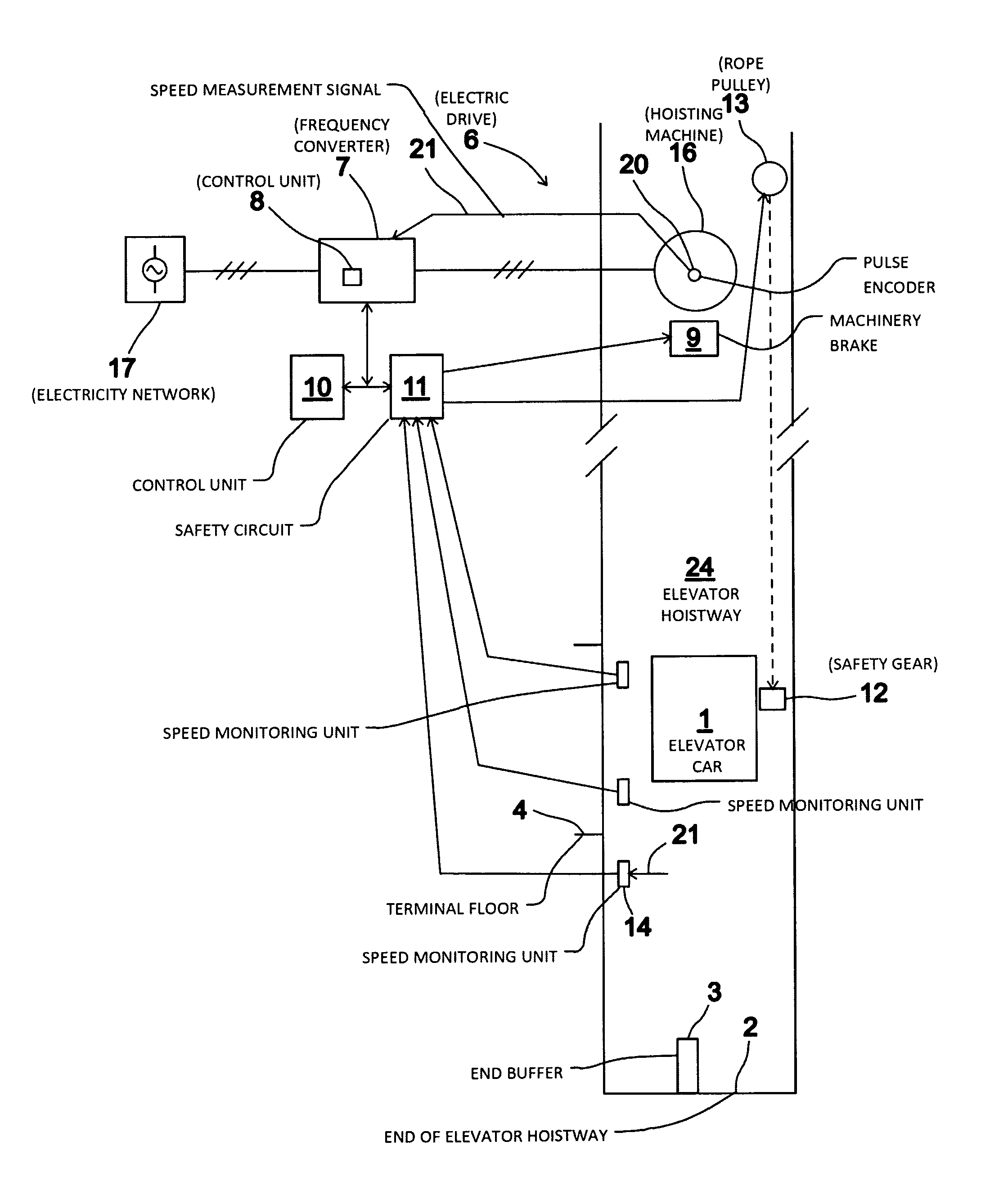
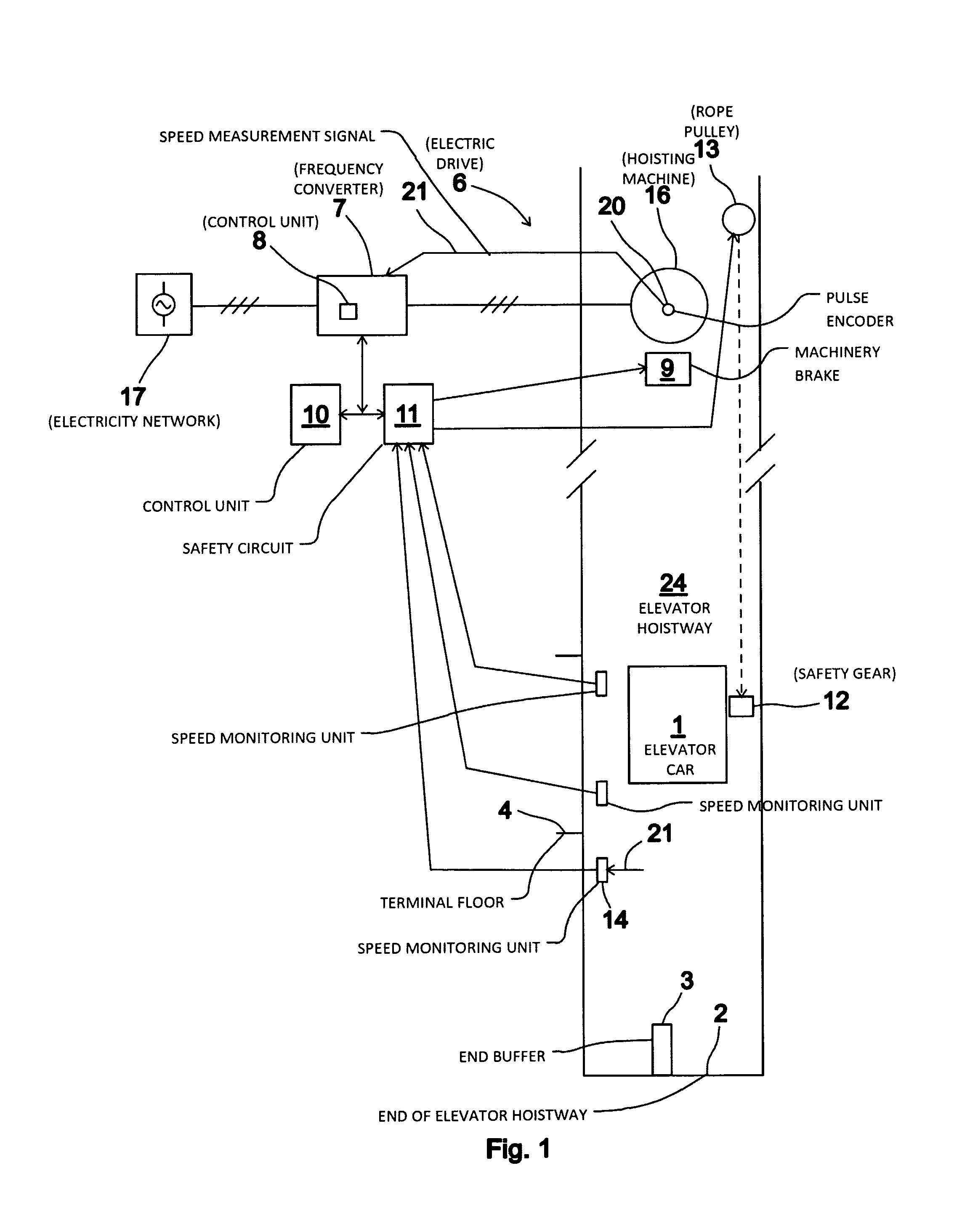
[0030]FIG. 1 presents as a block diagram an elevator system according to a first embodiment of the invention, wherein the elevator car 1 is moved in the elevator hoistway 24 with an electric drive 6, which comprises the hoisting machine 16 of the elevator and also a frequency converter 7. The elevator car 1 and the counterweight 18 are suspended in the elevator hoistway 24 with hoisting ropes, a belt or corresponding (not shown in the figure) passing via the traction sheave of the hoisting machine 16 of the elevator. The power supply to the electric motor of the hoisting machine 16 of the elevator occurs with a frequency converter 7 from an electricity network 17. The control unit 10 of the elevator calculates the target value for speed, i.e. the speed reference, of the elevator car 1 to be moved in the elevator hoistway 24 and the frequency converter 7 adjusts the speed of the hoisting machine 16, and thereby indirectly also the speed of the elevator car 1, towards the aforemention...

embodiment 2

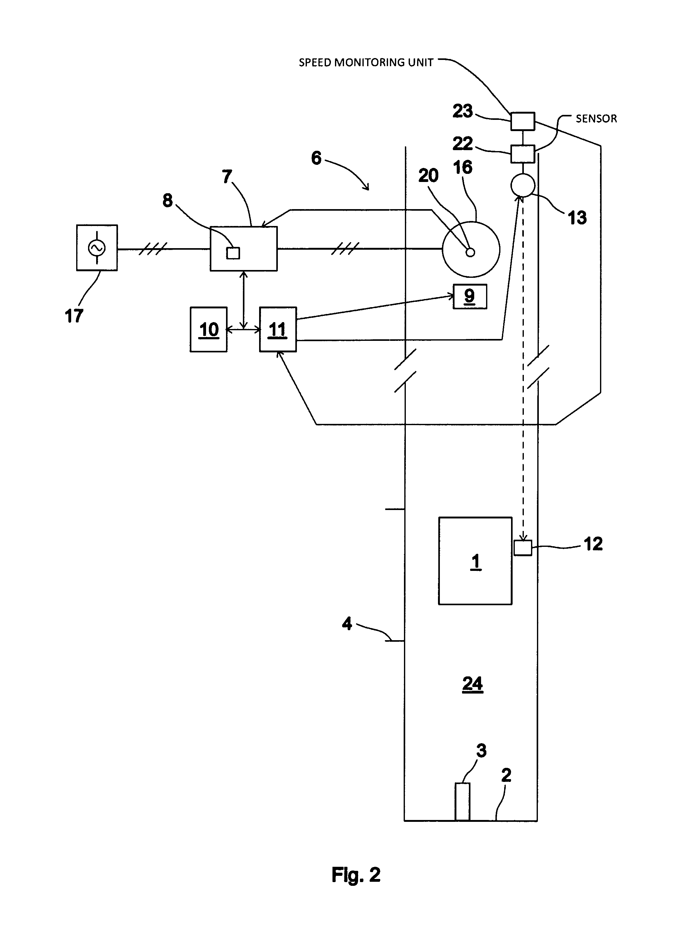
[0041]FIG. 2 presents as a block diagram an elevator system according to a second embodiment of the invention, wherein the elevator car 1 is moved in the elevator hoistway 24 with an electric drive 6, which comprises the hoisting machine 16 of the elevator and also a frequency converter 7. The elevator car 1 and the counterweight 18 are suspended in the elevator hoistway 24 with hoisting ropes, a belt or corresponding (not shown in the figure) passing via the traction sheave of the hoisting machine 16 of the elevator. The power supply to the electric motor of the hoisting machine 16 of the elevator occurs with a frequency converter 7 from an electricity network 17. The control unit 10 of the elevator calculates the target value for speed, i.e. the speed reference, of the elevator car 1 to be moved in the elevator hoistway 24 and the frequency converter 7 adjusts the speed of the hoisting machine 16, and thereby indirectly also the speed of the elevator car 1, towards the aforementio...


PUM


Abstract

The invention relates to an elevator system and also to a method for monitoring the movement an elevator car. In the method a first emergency braking procedure is activated for braking the elevator car at a first deceleration if the speed of the elevator car exceeds the first limit value for permitted speed, and also a second emergency braking procedure is further activated for braking the elevator car at a second deceleration that is greater than the first, if the speed of the elevator car exceeds the second limit value for permitted speed that is greater than the first limit value for permitted speed.

Description

CROSS-REFERENCE TO RELATED APPLICATIONS[0001]This is a Continuation of PCT / FI2011 / 000003 filed on Jan. 18, 2011, which is an International Application claiming priority from FI 20105033 filed on Jan. 18, 2010; the entire contents of each of which are hereby incorporated by reference.FIELD OF THE INVENTION[0002]The invention relates to the safety of elevators and more particularly to the monitoring of the movement of an elevator car.BACKGROUND OF THE INVENTION[0003]The electric drive of an elevator attends to the moving of an elevator car in an elevator hoistway between stopping floors. The control system of the elevator forms a target value for the speed of the elevator car, i.e. a speed reference, for the electric drive. The speed reference can be divided into the acceleration phase of a run, the phase of even speed, and also the deceleration phase. The control system of the elevator starts the deceleration phase of a run when the elevator car has arrived at a predefined distance f...

Claims


Application Information

Patent Timeline
Patent Type & Authority Patents(United States)
IPC IPC(8): B66B1/34
CPCB66B5/04B66B1/34B66B1/32B66B5/18B66B5/02
Inventor HARKONEN, ARIVALJUS, PETTERI
Owner KONE CORP
Why Eureka
Try Eureka