
Vehicle travel control device and vehicle travel control method

a technology of vehicle travel control and control device, which is applied in the direction of brake systems, instruments, machines/engines, etc., can solve the problems of passenger discomfort of the subject vehicle, and achieve the effect of improving the followability to the set target acceleration

Inactive Publication Date: 2009-05-07
TOYOTA JIDOSHA KK
View PDF5 Cites 7 Cited by
  • Summary
  • Abstract
  • Description
  • Claims
  • Application Information

AI Technical Summary

Benefits of technology

The present invention relates to a vehicle travel control device and method that can smoothly accelerate and decelerate the vehicle based on the driver's intentions and the vehicle's current state. The device sets a target acceleration and uses a limit value to control the vehicle's speed. When there is a large difference between the target acceleration and the actual acceleration, the device can experience sudden acceleration or deceleration, which can make the passenger uncomfortable. The invention proposes a solution to this problem by setting a higher limit value for the target acceleration when the difference between the target acceleration and the actual acceleration is large, so that the vehicle can smoothly accelerate or decelerate and improve its followability to the driver's intentions.

Problems solved by technology

When the subject vehicle cannot accelerate and decelerate smoothly, a passenger of the subject vehicle feels uncomfortable.

Method used


Image

  • Vehicle travel control device and vehicle travel control method
  • Vehicle travel control device and vehicle travel control method
  • Vehicle travel control device and vehicle travel control method

Examples


embodiment

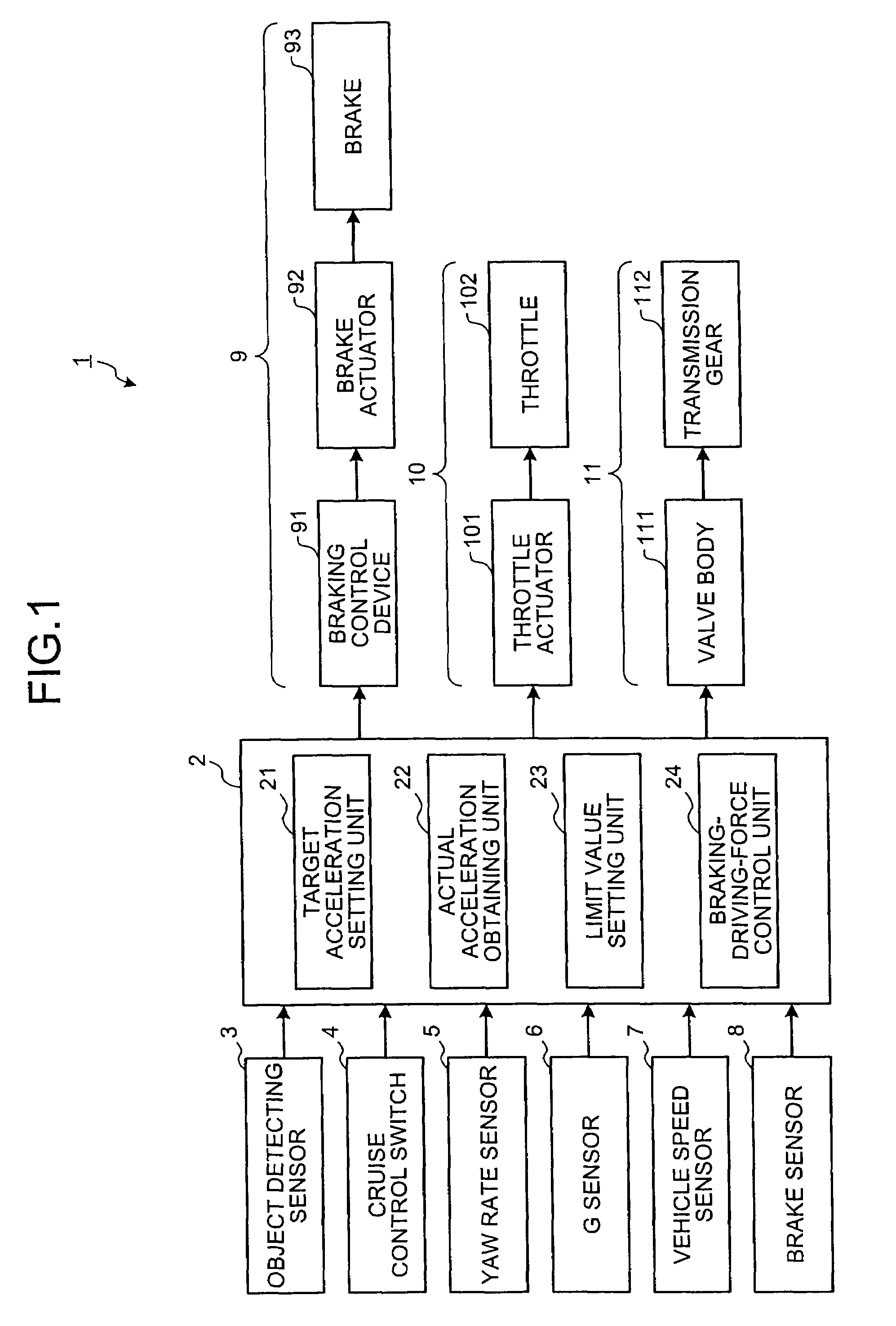
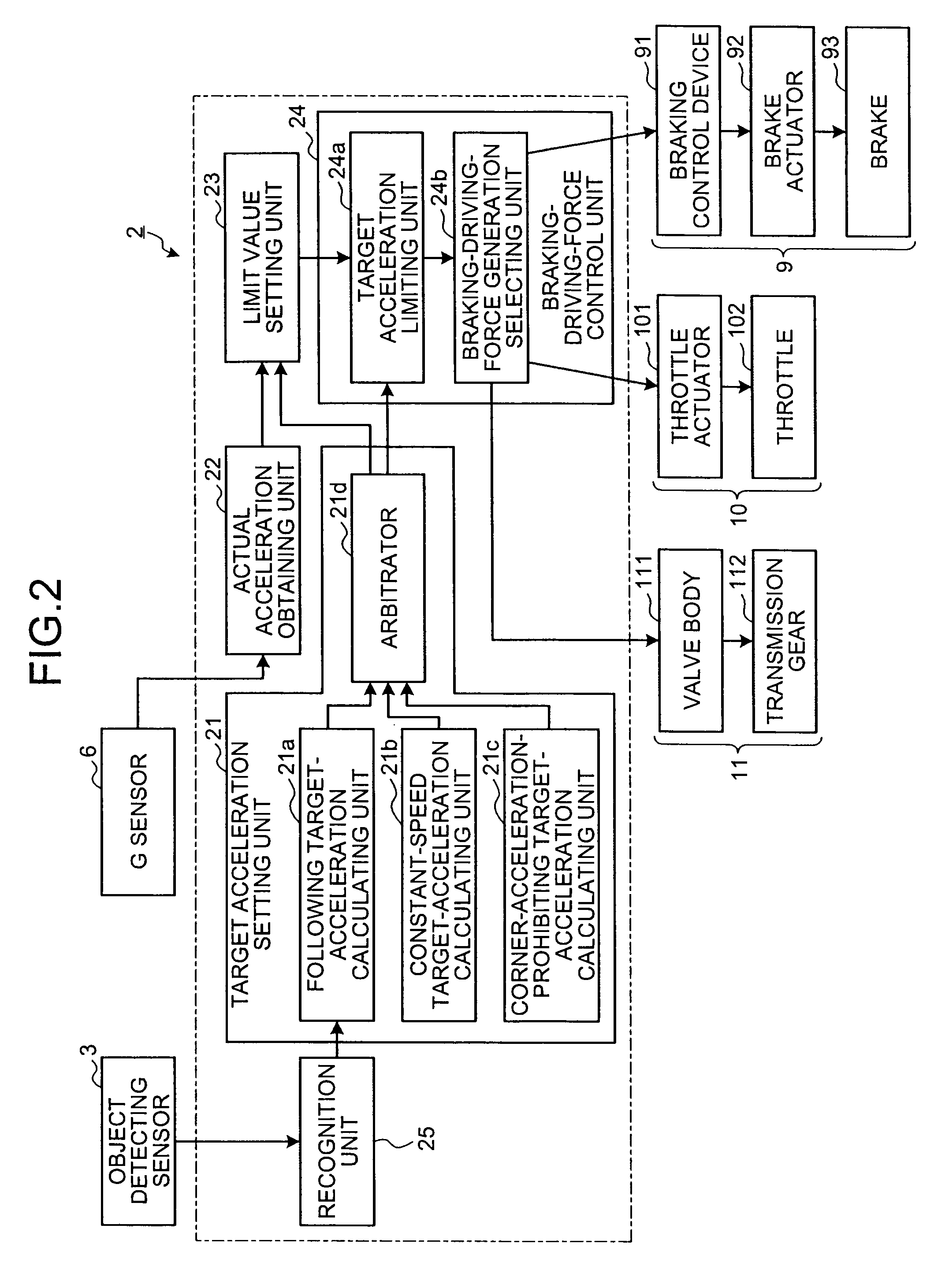
[0058]FIGS. 1 and 2 are block diagrams of a configuration example of a vehicle travel control device according to the present invention. As shown in FIGS. 1 and 2, a vehicle travel control device 1 according to the present invention is mounted on a subject vehicle not shown and performs vehicle travel control, in other words, ACC, to reduce driving operations of the subject vehicle by a driver. The vehicle travel control device 1 includes a control device 2, an object detecting sensor 3, a cruise control switch 4, a yaw rate sensor 5, a G sensor 6, a vehicle speed sensor 7, a brake sensor 8, a braking device 9, a throttle device 10, and a transmission device 11. The ACC includes a constant-speed travel control which makes the subject vehicle drive at a set speed, and a forward-vehicle following travel control which makes the subject vehicle drive in pace with a vehicle ahead.

[0059]The control device 2 controls the vehicle travel control device 1 as a whole. Further, the control devi...


PUM


Abstract

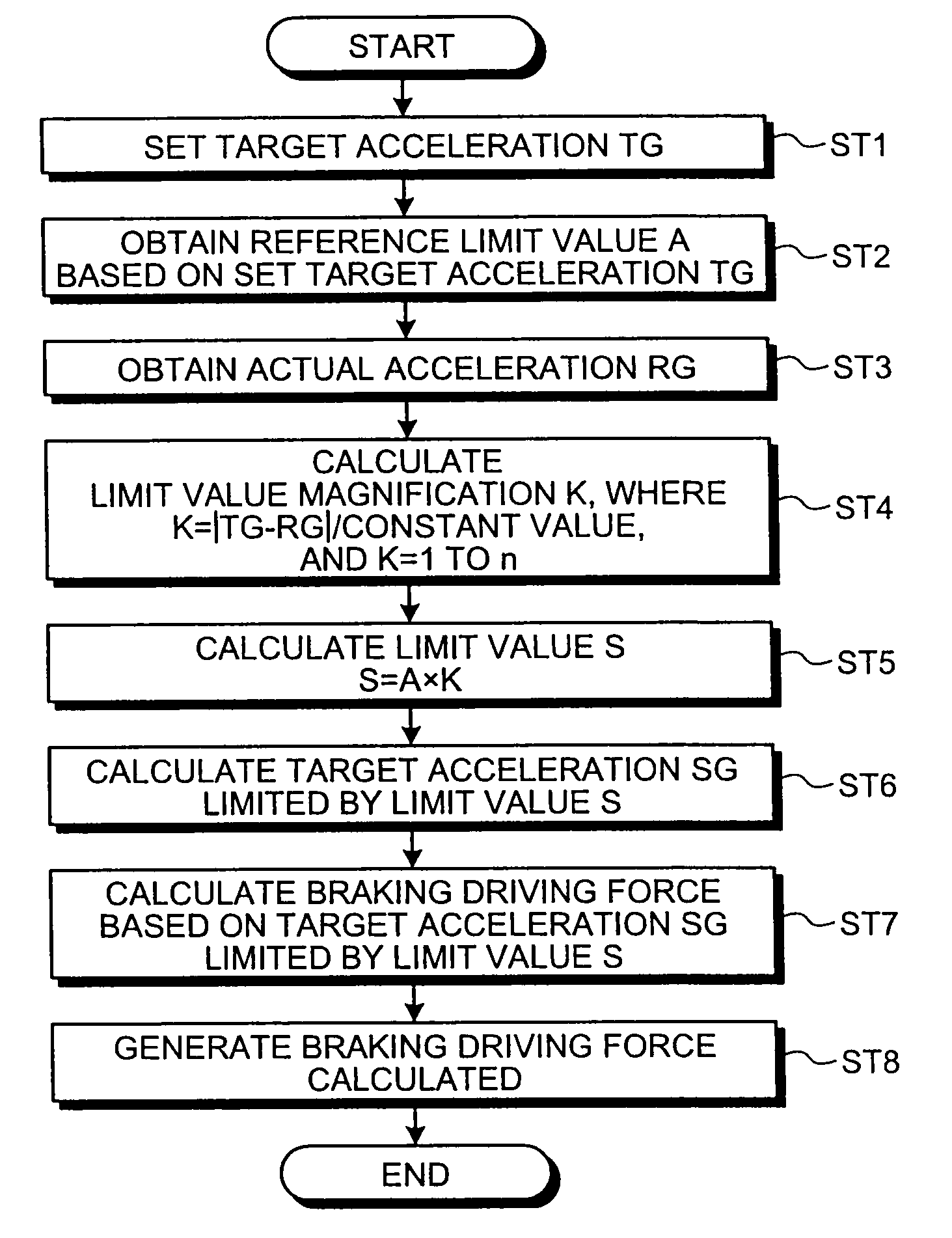
Target acceleration of a subject vehicle is set; a reference limit value is obtained based on the set target acceleration; actual acceleration of the subject vehicle is obtained; a limit value magnification is calculated so that a limit value for limiting a change of the target acceleration becomes larger as a difference between the set target acceleration and the detected actual acceleration becomes larger; the limit value is calculated; the set target acceleration is limited based on the set limit value; a braking driving force is calculated based on the limited target acceleration; and the calculated braking driving force is generated by a selected braking driving force generating unit. Smooth acceleration and deceleration of the vehicle can be performed according to a travel state of the vehicle, and followability to the set target deceleration can be improved.

Description

TECHNICAL FIELD[0001]The present invention relates to a vehicle travel control device and a vehicle travel control method, and more particularly, to a vehicle travel control device and a vehicle travel control method that set a target acceleration and generate a braking driving force corresponding to the set target acceleration.BACKGROUND ART[0002]On a conventional vehicle, a vehicle travel control device is mounted as a unit for reducing driving operations by a driver on a subject vehicle. The vehicle travel control device performs vehicle travel control by, for example, making the subject vehicle running at a set speed, or running in pace with a vehicle ahead, in other words, the vehicle travel control device performs adaptive cruise control (ACC). In the ACC, target acceleration is set depending on a travel state of the subject vehicle. For example, the acceleration is set corresponding to preset speed, or set to allow the subject vehicle keep pace with a vehicle ahead. An engine...

Claims


Application Information

Patent Timeline
Patent Type & Authority Applications(United States)
IPC IPC(8): G06F19/00B60T7/12B60W10/00B60W10/04B60W10/06B60W10/10B60W10/18B60W10/184B60W30/00B60W30/14F02D29/02
CPCB60T7/12B60T7/22B60T2201/02F02D29/02B60W40/107B60W2420/52B60W2720/106B60W30/16B60W2420/408
Inventor ABE, KYOICHI
Owner TOYOTA JIDOSHA KK
Learn More