Motor vehicle automated gearbox and method for the operation thereof

a technology for motor vehicles and gearboxes, applied in gearing control, mechanical equipment, gearing, etc., can solve the problems of unfavorable automatic gearbox operation, so as to reduce the load on the automatic gearbox, compactly dimension, and increase the load on the drive motor.

Inactive Publication Date: 2012-06-12
ZF FRIEDRICHSHAFEN AG
View PDF18 Cites 9 Cited by
  • Summary
  • Abstract
  • Description
  • Claims
  • Application Information

AI Technical Summary

Benefits of technology

[0011]By at least partially engaging the change-under-load clutch, during a shift process between two gears which contain at most one direct step (ratio i=1), when the engine clutch is engaged, the torque transmitted from the drive motor via the engine clutch to the input shaft can, for the most part, be taken up. In this way, the shift clutch of the loaded, engaged gear is relieved of its load and can, therefore, be disengaged largely free from load in order to disengage the loaded gear. Likewise, the target gear to be engaged can thereby be synchronized while largely free from load and then engaged. By virtue of the transmission structure according to the invention. The shift processes can be carried out as partial changes-under-load without interrupting the force flow, provided they do not involve any overdrive step (i<1). This avoids any undesired deceleration or acceleration of the motor vehicle so that the shift process can be carried out on the whole more quickly and more comfortably.
[0012]Since the loading of the drive train is maintained, load surges and fluctuations are also avoided such that there is reduced wear on critical components of the drive train and greater overall driving comfort. Other devices provided to reduce the input speed of the shift transmission during gearshift processes, such as a transmission brake or an engine brake, can be omitted, which represents a saving.
[0013]The change-under-load clutch is preferably made as a pressure-controlled disk clutch, since such a structure has compact dimensions and, especially in relation to the transferable torque, can be controlled simply and accurately.
[0020]Once the loaded gear has been disengaged, synchronization of the target gear can be carried out or at least assisted by changing the torque transferred by the change-under-load clutch. To synchronize the target gear the change-under-load clutch is engaged a bit further during an upshift process and disengaged a bit further during a downshift process. By engaging the change-under-load clutch further, the load on the drive motor is increased and, therefore, the drive train on the input side is slowed down. By disengaging the change-under-load clutch further, the load on the automated gearbox is reduced and the drive train on the input side is accelerated by the faster-running drive motor. Thanks to such synchronization support, the customary synchronization means, such as frictional synchronization devices associated with the shift clutches, can be more compactly dimensioned since the load on them is lower or, in some cases, they can be omitted entirely.

Problems solved by technology

A disadvantage in shift transmissions, however, is the structure-entailed interruption of the force flow between the drive motor and the drive axle connected with the output shaft of the transmission during a gear change, which occurs because the engine coupling is temporarily disengaged and the shift transmission is briefly in its neutral position.
During an upshift, especially an upshift in traction while driving uphill, this can result in an undesired deceleration of the motor vehicle and, during a downshift, especially a downshift while coasting downhill, to an undesired acceleration of the motor vehicle.
In general this leads to a delay and to an uncomfortable course of the shift process.
For that reason, particularly in the case of commercial vehicles and to shorten the force interruption, it is known to accelerate synchronization of the respective gear to be engaged in an upshift by way of a transmission brake or, with the engine clutch engaged, by acting on the control of the engine by way of an engine brake, but this entails greater cost and complexity for the additional equipment.

Method used


Image

  • Motor vehicle automated gearbox and method for the operation thereof
  • Motor vehicle automated gearbox and method for the operation thereof
  • Motor vehicle automated gearbox and method for the operation thereof

Examples


Embodiment Construction

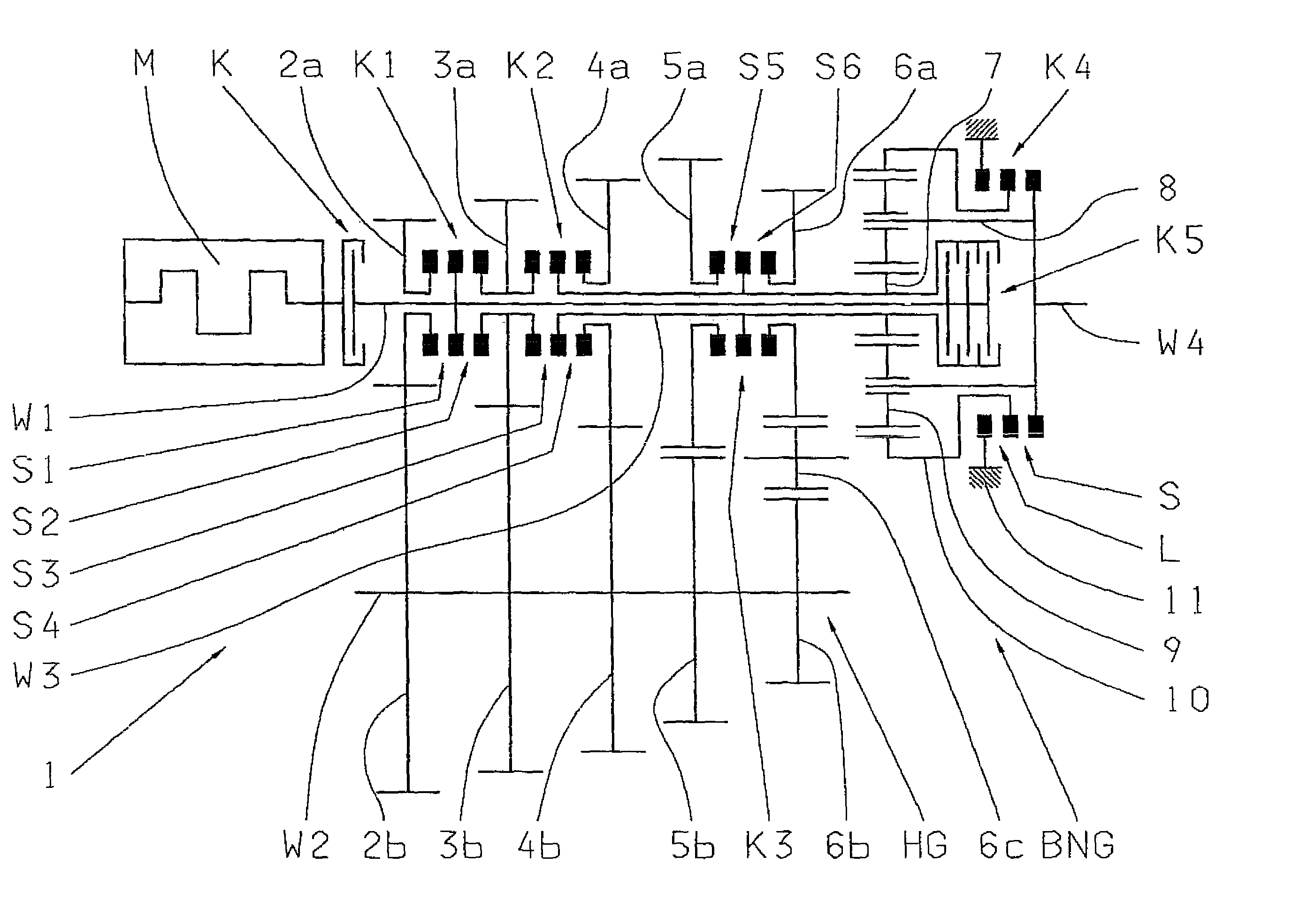
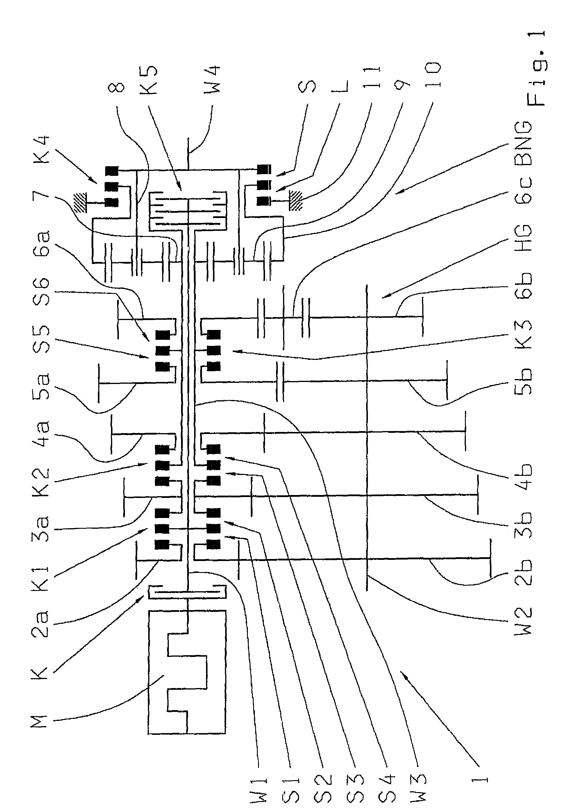
[0024]An automated gearbox 1, according to FIG. 1, is formed as a range-change gearbox with a main gearbox HG and a range group BNG connected downstream therefrom. The main gearbox HB, which has four forward gears and one reverse gear, is provided with an input shaft W1, a countershaft W2 arranged parallel thereto, and an output shaft W3 arranged co-linearly or co-axially to the input shaft W1. In this case, the output shaft W3 is made as a hollow shaft and the input shaft W1 extends centrally inside the output shaft W3 as far as the output side end of the output shaft W3 and the main gearbox HG.

[0025]On the input side, the input shaft W1 of the main gearbox is connected to a drive motor M, made as a combustion engine, by an engine clutch K that can be engaged and disengaged. Inside the gearbox, the input shaft W1 can be coupled in a shift position S1, via a first shift clutch K1, to a loose gear wheel 2a of a first gear wheel pair 2a, 2b where, owing to the fixed connection of the ...


PUM


Abstract

The invention concerns an automated motor vehicle shift transmission (1) with an input shaft, an output shaft and several selectively engaged gears, the input shaft (W1) being connected to a drive motor (M) via an engine clutch (K) that can be engaged and disengaged. To avoid an interruption of the traction force during a shift process, a controllable friction clutch is provided as a change-under-load clutch (K5) to connect the input shaft (W1) directly to the output shaft (W3, W4) when necessary.The invention also concerns a method for controlling the gearshifts of an automated motor vehicle shift transmission comprising an input shaft, an output shaft and several selectively engaged gears, and in which the input shaft is connected to a drive motor via an engine clutch that can be engaged or disengaged, such that in a shift process between a loaded gear that is engaged and a target gear to be engaged, the engine clutch remains closed during the gear change. To avoid a traction force interruption it is provided that during a shift process between two gears containing at most one direct step (i>=1), before the loaded gear is disengaged a change-under-load clutch, positioned between the input shaft (W1) and the output shaft (W3, W4), is at least partially closed in order to take over the torque transfer, the loaded gear is then disengaged, the target gear is then synchronized and engaged, and finally the change-under-load clutch (K5) is fully opened again.

Description

[0001]This application is a national stage completion of PCT / EP2006 / 008220 filed Aug. 21, 2006, which claims priority from German Application Serial No. 10 2005 046 894.2 filed Sep. 30, 2005.FIELD OF THE INVENTION[0002]The invention concerns an motor vehicle automated gearbox, with an input shaft, an output shaft and several gears that can be selectively engaged. The input shaft is connected with a drive motor via an engine clutch that can be engaged and disengaged.[0003]The invention also concerns a method for controlling the gearshifts of a motor vehicle automated gearbox, which comprises an input shaft, an output shaft and several selectively engaged gears. The input shaft is connected to a drive motor via an engine clutch that can be engaged and disengaged, such that the engine clutch remains engaged during a shift process between a gear engaged under load and a target gear to be engaged.BACKGROUND OF THE INVENTION[0004]Automated shift transmissions are increasingly used in both...

Claims


Application Information

Patent Timeline
Patent Type & Authority Patents(United States)
IPC IPC(8): F16H3/44F16H37/02F16H3/08
CPCF16H3/12F16H37/046F16H61/04F16H2003/007F16H2003/0818Y10T74/19228F16H2061/0429F16H2306/48Y10T477/69335Y10T74/19223F16H2061/0425F16H3/091F16H3/00F16H37/04
Inventor HEINZELMANN, KARL-FRITZ
Owner ZF FRIEDRICHSHAFEN AG
Why Eureka
Try Eureka