Shift control system and method for automated manual transmission

a technology of automatic transmission and control system, which is applied in the direction of gearing control, gearing element, belt/chain/gearing, etc., can solve the problems of reducing the driving performance, affecting the clutch, and reducing the shift duration, so as to improve the driving performance, increase the deceleration, and minimize the shift duration

Inactive Publication Date: 2013-01-03
HYUNDAI MOTOR CO LTD
View PDF1 Cites 7 Cited by
  • Summary
  • Abstract
  • Description
  • Claims
  • Application Information

AI Technical Summary

Benefits of technology

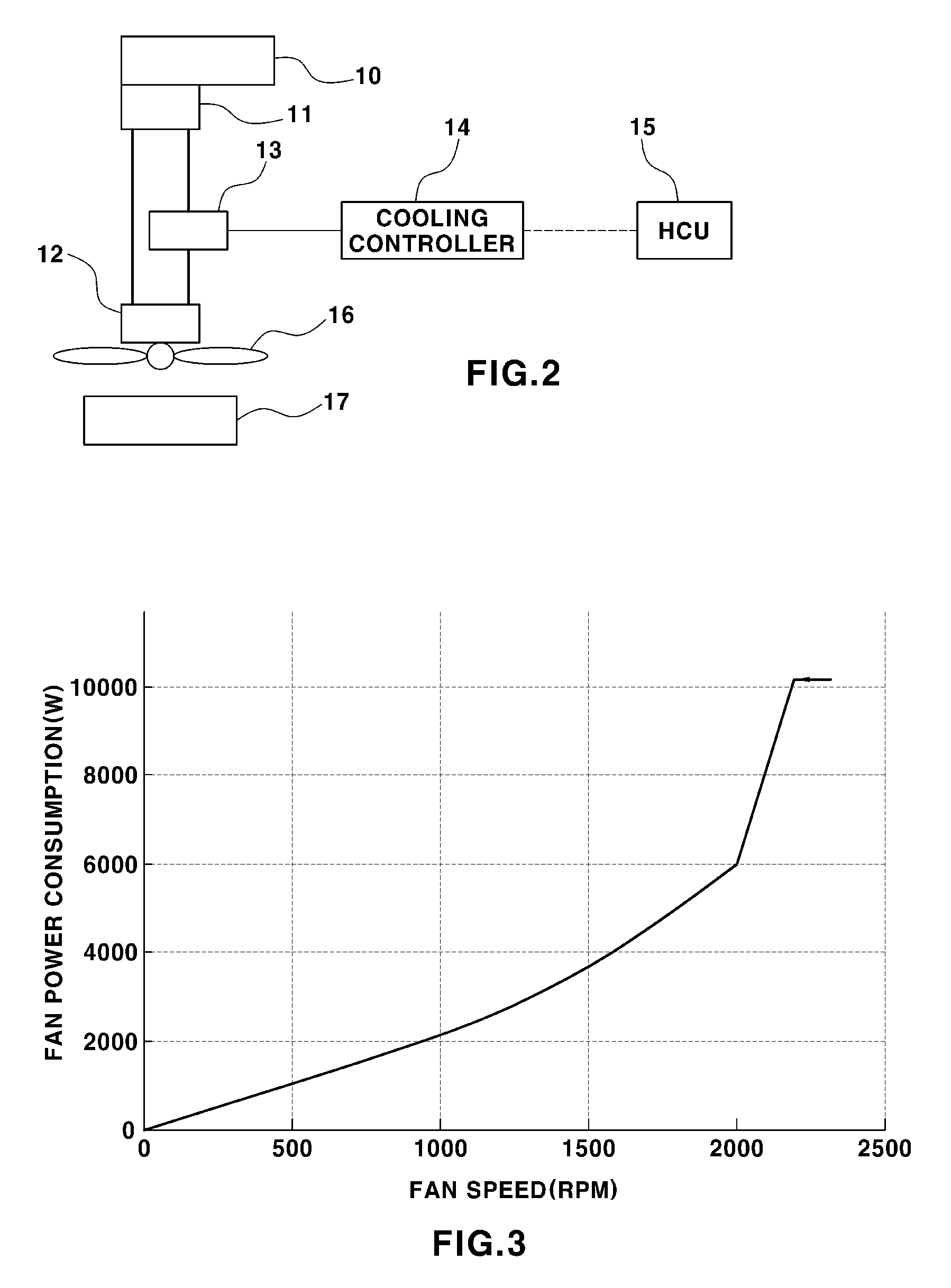
[0012]The present invention provides a shift control system and method for an automated manual transmission, which can minimize shift duration by increasing the deceleration of an engine and improving the driving performance by shortening power interruption duration upon shifting, by operating a cooling fan upon shifting to increase an engine load.
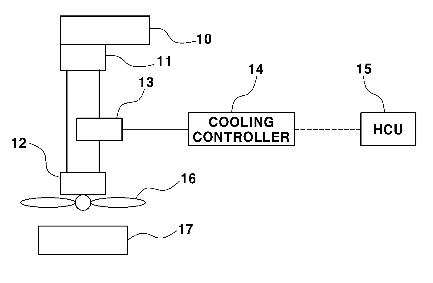
[0014]In an exemplary embodiment, the engine speed may be reduced by requesting a signal which fully opens the open / close (first) valve from a cooling controller when a hybrid control unit receives a signal at the beginning of the shifting and the release of the clutch from a transmission control unit. A hydraulic pump is then operated via an engine when the open / close valve connected between the hydraulic pump and a hydraulic motor is fully opened via a request from a hybrid control unit which produces an open signal. A cooling fan using a turning force of the hydraulic motor is then operated via a hydraulic motor using a hydraulic pressure generated in the hydraulic pump.

Problems solved by technology

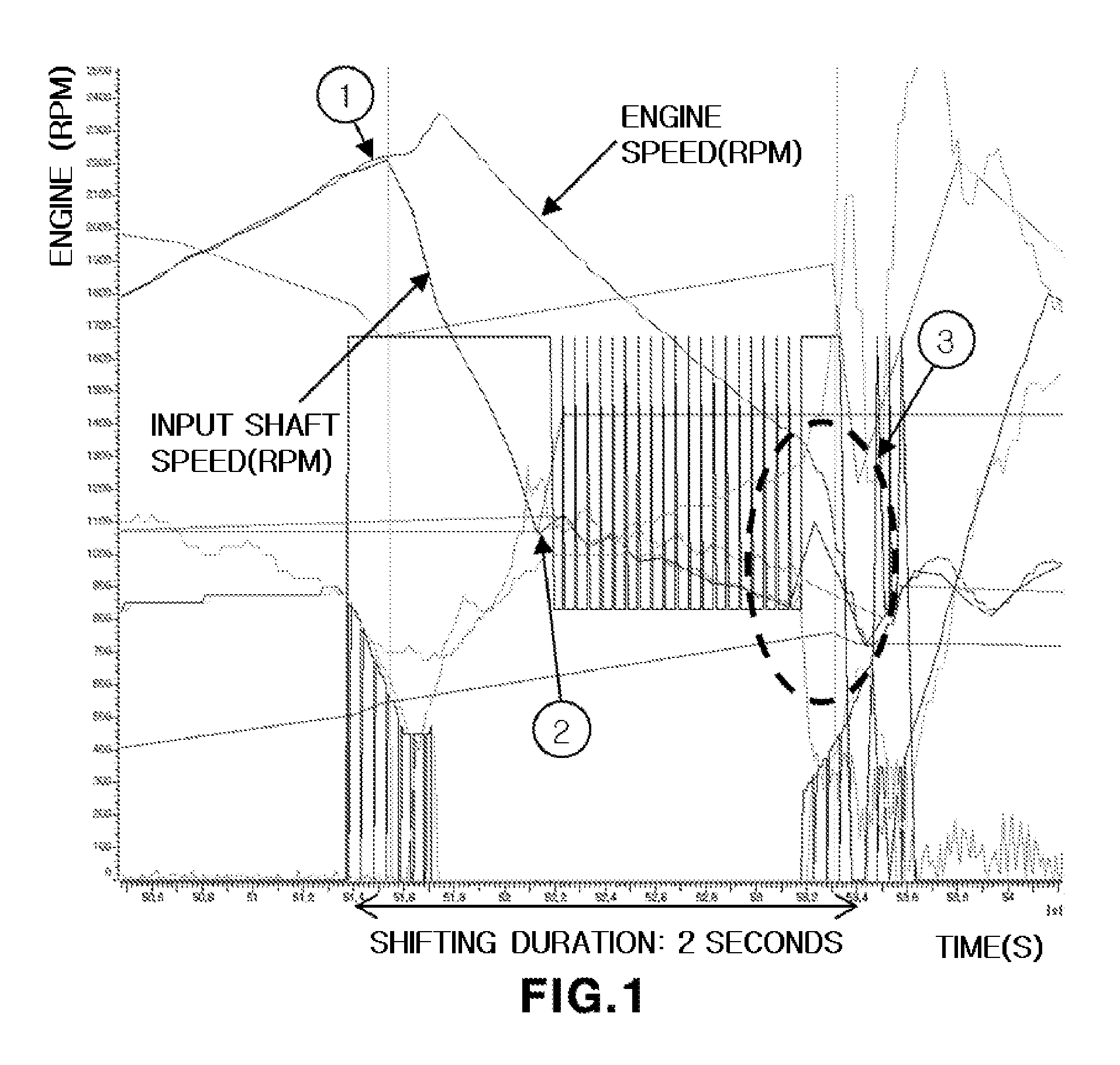
However, an AMT that is gear-shifted according to the above control method has an advantage of low power loss due to better power transmission efficiency than an automatic transmission, but also has a limitation in reduction of drivability due to interruption of power transmission during the shifting.
Accordingly, the shifting duration is elongated, and the synchronization between the input shaft speed and the engine speed is also delayed, causing an impact upon rejoining of the clutch.

Method used


Image

  • Shift control system and method for automated manual transmission
  • Shift control system and method for automated manual transmission
  • Shift control system and method for automated manual transmission

Examples


Embodiment Construction

[0033]Hereinafter reference will now be made in detail to various embodiments of the present invention, examples of which are illustrated in the accompanying drawings and described below. While the invention will be described in conjunction with exemplary embodiments, it will be understood that present description is not intended to limit the invention to those exemplary embodiments. On the contrary, the invention is intended to cover not only the exemplary embodiments, but also various alternatives, modifications, equivalents and other embodiments, which may be included within the spirit and scope of the invention as defined by the appended claims.

[0034]It is understood that the term “vehicle” or “vehicular” or other similar term as used herein is inclusive of motor vehicles in general such as passenger automobiles including sports utility vehicles (SUV), buses, trucks, various commercial vehicles, watercraft including a variety of boats and ships, aircraft, and the like, and inclu...


PUM


Abstract

A shift control system and method for a vehicle equipped with an automated manual transmission is disclosed herein. In the shift control system, upon determining that shifting has started and a clutch has been released, an engine speed is reduced by fully opening a valve of a hydraulic cooling unit when. The engine speed is then synchronized with an input shaft speed and the clutch is rejoined once the engine speed is synchronized with the input shaft speed.

Description

CROSS-REFERENCE TO RELATED APPLICATION[0001]This application claims under 35 U.S.C. §119(a) the benefit of Korean Patent Application No. 10-2011-0065169 filed Jun. 30, 2011, the entire contents of which are incorporated herein by reference.BACKGROUND[0002](a) Technical Field[0003]The present invention relates to a shift control method for an automated manual transmission. More particularly, it relates to a shift control method for an automated manual transmission, which can improve driving performance by reducing duration of interruption of power transmission during shifting.[0004](b) Background Art[0005]Large commercial vehicles have been increasingly adopting Automated Manual Transmissions (AMTs) in order to improve fuel efficiency, power performance, and driver's convenience. An automated manual transmission (also known as self-changing transmission, clutchless manual transmission, flappy-paddle gearbox, or paddle-shift gearbox) is a system which uses electronic sensors, pneumati...

Claims


Application Information

Patent Timeline
Patent Type & Authority Applications(United States)
IPC IPC(8): B60W10/02B60W10/06
CPCF16H61/682F16H63/40Y10T477/6422F16H2059/6807F16H61/0403F16H61/28F16H61/04
Inventor SUNG, BYUNG JUNJANG, SANG PIL
Owner HYUNDAI MOTOR CO LTD
Why Eureka
Try Eureka