
Fitting confirmation construction of connector for connecting circuit board

a technology for connecting circuit boards and connectors, which is applied in the direction of coupling device connections, coupling device details, engagement/disengagement of coupling parts, etc., can solve the problems of difficult visual confirmation of whether or not both connectors are properly fitted together by looking at the external appearance of the connector, and the cost involved becomes high, so as to save resin material resources, simple connector construction, and easy to use

Active Publication Date: 2014-06-24
YAZAKI CORP
View PDF15 Cites 10 Cited by
  • Summary
  • Abstract
  • Description
  • Claims
  • Application Information

AI Technical Summary

Benefits of technology

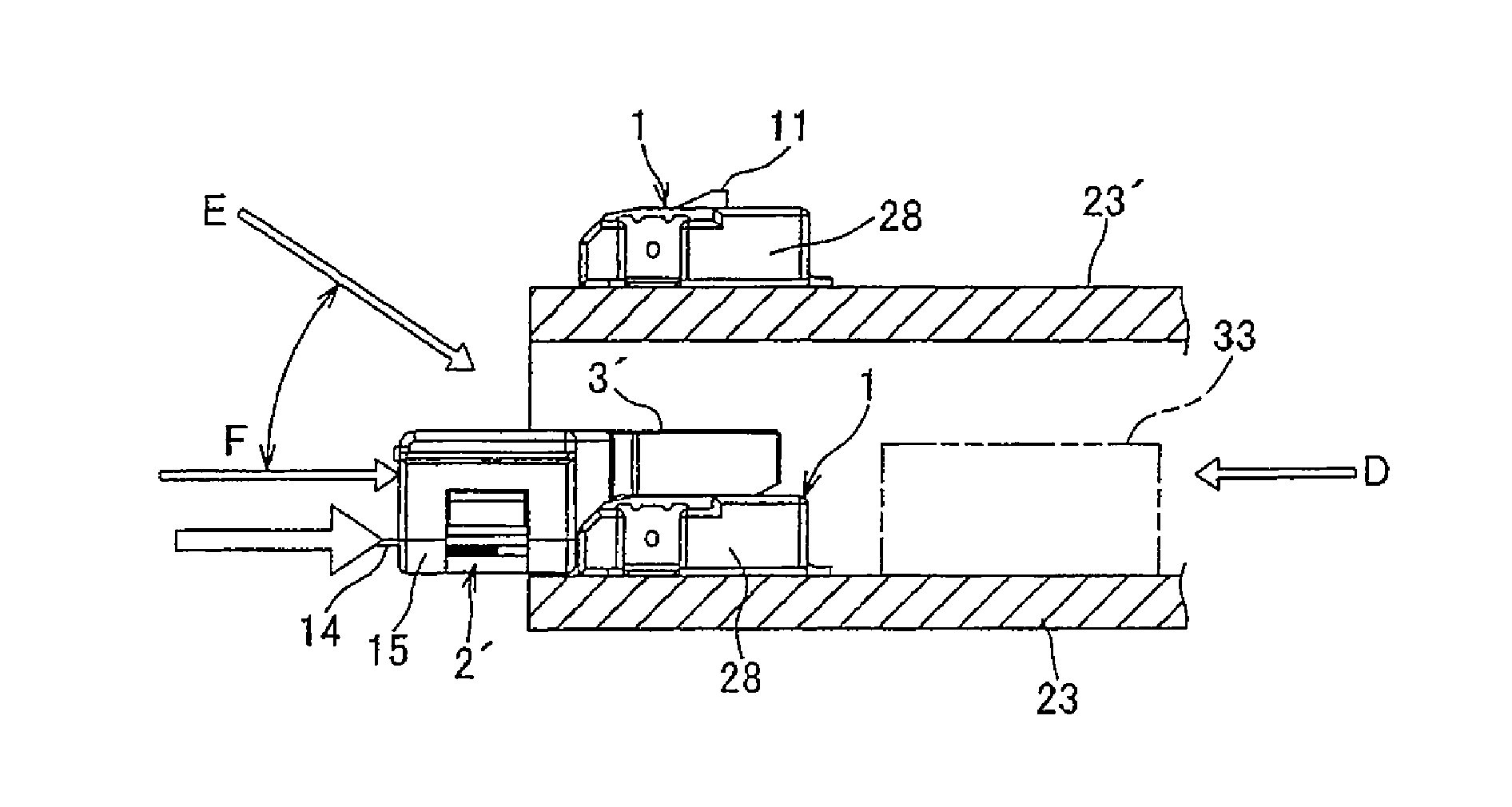
The present invention provides a circuit board connection confirmation construction that allows for easy and secure visual confirmation of proper connectors' fitting connection, even when the connectors cannot be directly observed from the front or from above. The visual confirmation of the connectors is achieved by using confirmation openings in the connectors' housing that are simple and low-cost to construct. The invention also provides a lightweight and resource-conserving construction by using confirmation openings that extend as far as the arm protection wall of the housing. Additionally, the invention allows for the visual confirmation of the connectors' oblique fitting connection by using the location of the confirmation openings and the position of the worker's stand.

Problems solved by technology

The visual confirmation from the obliquely upper position at the rear causes a problem that the visual confirmation on whether or not both the connectors are fitted together properly by looking at the external appearance thereof is difficult.
In addition, the way of confirming the proper connectors fitting connection by visually confirming the movement of the marked arm as described in PTL 3 or the differently colored housing as described in PTL 4 has caused a problem that costs involved become high.

Method used


Image

  • Fitting confirmation construction of connector for connecting circuit board
  • Fitting confirmation construction of connector for connecting circuit board
  • Fitting confirmation construction of connector for connecting circuit board

Examples


Embodiment Construction

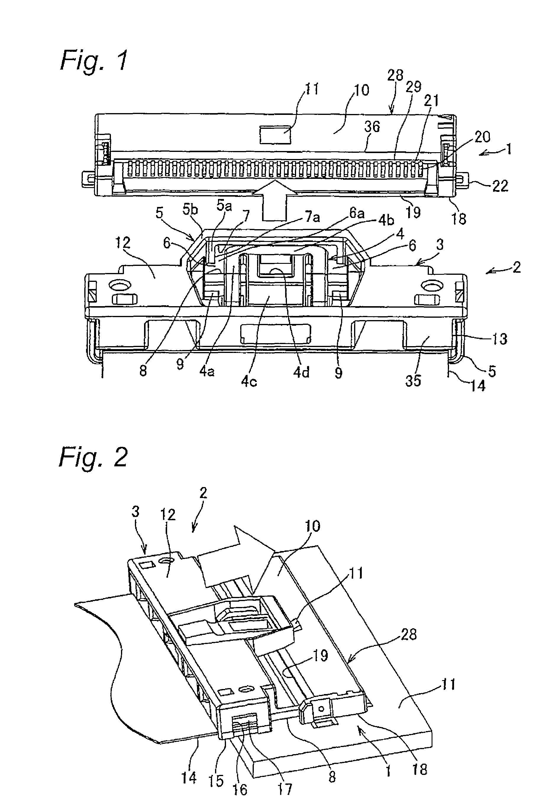
[0040]FIGS. 1 to 9 show an embodiment of a circuit board connecting connector fitting confirmation construction according to the invention. FIG. 1 shows a state resulting before a flat-circuit-element-side connector 1 is fitted to a circuit-board-side connector 1, the connectors 1, 2 being seen from an obliquely upper position at the rear. The circuit-board-side connector 1 and the flat-circuit-element-side connector 2 make up a circuit board connecting connector.

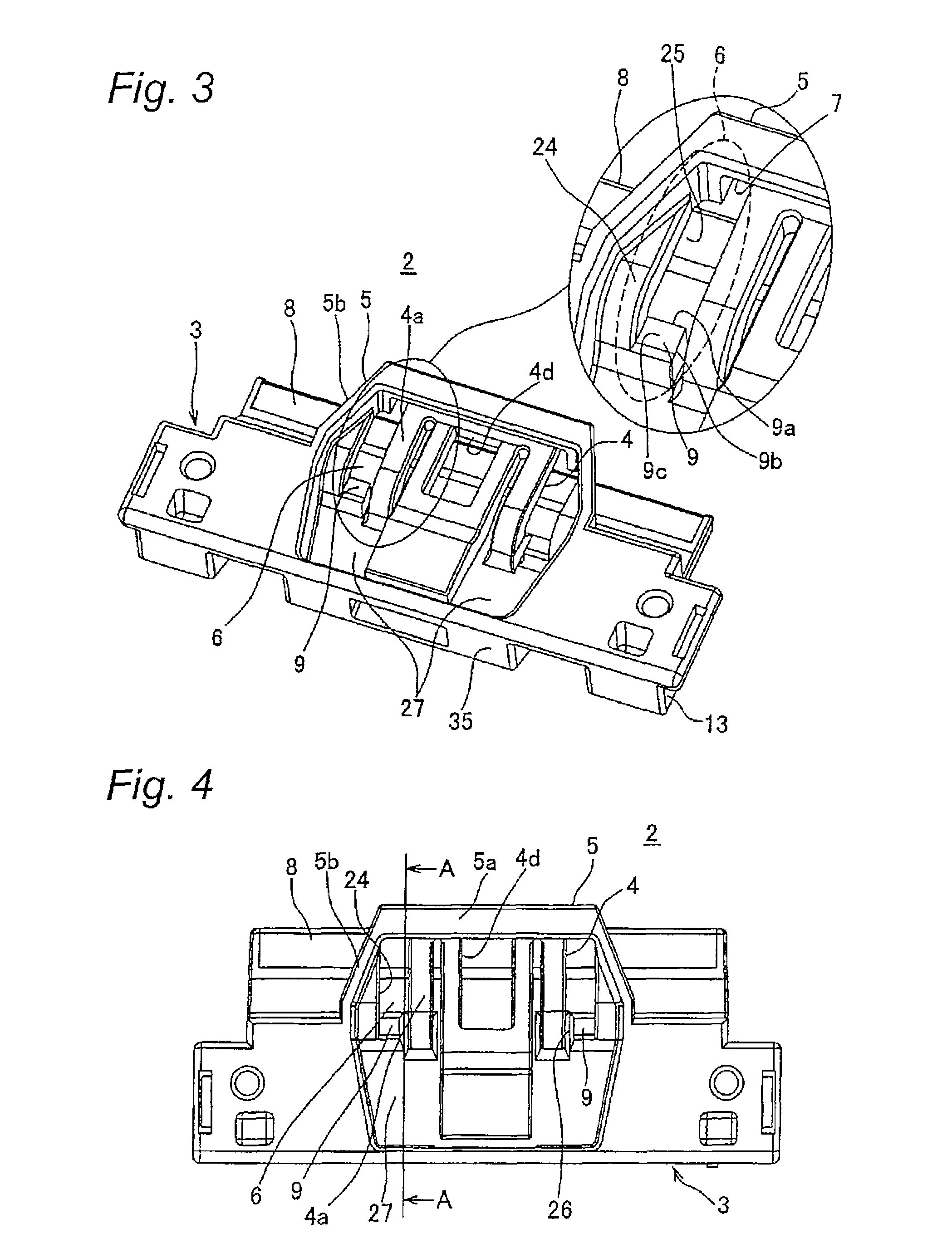
[0041]As is shown in FIG. 1, in a construction in which the flat-circuit-element-side connector 2 is fitted forwards as indicated by an arrow to the circuit-board-side connector 1, this circuit board connecting connector fitting confirmation construction is such that an upper opening (a confirmation opening) 6 is provided on each of left- and right-hand sides of a flexible lock arm 4 which is provided in a center in a width direction of a housing 3 formed of insulating resin of the flat-circuit-element-side connector 2 betw...


PUM


Abstract

A fitting confirmation construction includes a confirmation part in a first connector and a confirmation opening in a second connector. A rib is provided in the confirmation opening. A height of the confirmation part is equal to a height of the rib and the confirmation part and the rib are positioned on a same line, on a viewing direction which is viewed from an obliquely upper position rearward in an inserting direction of the second connector through the confirmation opening, in a state that the second connector is completely fit with the first connector.

Description

CROSS REFERENCE TO RELATED APPLICATION[0001]This application is a continuation of PCT application No. PCT / JP2011 / 058369, which was filed on Mar. 25, 2011 based on Japanese Patent Application (No. 2010-072777) filed on Mar. 26, 2010, the contents of which are incorporated herein by reference. Also, all the references cited herein are incorporated as a whole.BACKGROUND OF THE INVENTION[0002]1. Technical Field[0003]The present invention is related to a fitting confirmation construction of a connector for connecting a circuit board. The fitting confirmation construction is used for implementing a visual confirmation of whether or not, for example, a flat-circuit-element-side connector is completely fitted to a circuit-board-side connector which is disposed between stacked circuit boards.[0004]2. Background Art[0005]Conventionally, various types of fitting confirmation constructions used in connecting a connector installed at an end of a flexible flat circuit element to a connector insta...

Claims


Application Information

Patent Timeline
Patent Type & Authority Patents(United States)
IPC IPC(8): H01R13/62
CPCH01R13/6272H01R12/79H01R13/641
Inventor OHYAMA, KOUICHI
Owner YAZAKI CORP
Learn More