
Bidirectional microphone system

a microphone and microphone technology, applied in the direction of substation equipment, electrical transducers, instruments, etc., can solve the problems of user injury or attack on criminal scene or accident site, user's rapid turning on and operating, and loss of recorded eviden

Inactive Publication Date: 2014-06-24
TAIWAN GOMET TECH
View PDF7 Cites 23 Cited by
  • Summary
  • Abstract
  • Description
  • Claims
  • Application Information

AI Technical Summary

Benefits of technology

The present invention provides a bidirectional microphone system that can be easily controlled and used in different modes. The system also includes a G-sensor that can automatically activate the microphone and video system in case of an emergency, ensuring the recording of useful evidences. The main advantage of this system is that it can be used even when the microphone is hindered by a heavy coat or bulletproof vest.

Problems solved by technology

It is very often policemen or firemen on duty get injured or attacked at criminal scene or accident site.
(1) The policemen or the firemen on duty usually wear the wireless microphone on their waist or put in a pocket, so that they may conveniently use the wireless microphone in performing their task. However, the police wireless microphone is also frequently covered by the user's heavy coat or raincoat in the winter or on rainy days, or by the user's bulletproof vest, preventing the user from quickly turning on and operating various functions of the wireless microphone.
(2) When a policeman or a fireman enters into a building with complicated internal structure or moves to a location out of the wireless signal receiving range in performing his task, the wireless microphone worn by the policeman or the fireman might fail to receive wireless signals or could only receive discontinuous wireless signals. Under this condition, not all the contents of the communication between the wireless microphone and the base station may be completely recorded. While the conventional wireless microphone is equipped with the digital recorder function to record important evidences, the recorded evidences is subject to lose if the wireless microphone is damaged or lost in a criminal scene when the policeman fights with a gangster.
(3) Some of the police wireless microphones are equipped with the global positioning system (GPS) function, so that the position coordinates of the policeman wearing the wireless microphone and moved away from the police car may be continuously sent back to the base station. However, in the event the policeman wears or puts the wireless microphone at an unsuitable position, or when the wireless microphone is undesirably covered or shielded by, for example, the user's body, a building or a big tree, it is very possible the wireless microphone loses its GPS function. Under this condition, while the wireless microphone may still transmit data back to the base station, persons at the base station would not be able to locate the user's exact position without the help of the GPS. In some worse conditions, the policeman or the fireman getting injured in the site could not be timely rescued because the base station fails to locate his position.
(4) There are chances the policeman on duty is accidentally hit by a car or attacked by a scoundrel, and the policeman does not have enough time to use the wireless microphone to remotely turn on the in-car video system on the police car. As a result, no evidence is recorded.
(5) There are also chances the policeman driving the police car to chase a gangster and moving beyond the transmission distance of the wireless microphone is badly injured and becomes unconscious. Since the injured policeman has moved beyond the communication distance of the wireless microphone, the injured policeman may be not timely rescued because the supporting persons fail to locate his accurate position.

Method used


Image

  • Bidirectional microphone system
  • Bidirectional microphone system
  • Bidirectional microphone system

Examples


Embodiment Construction

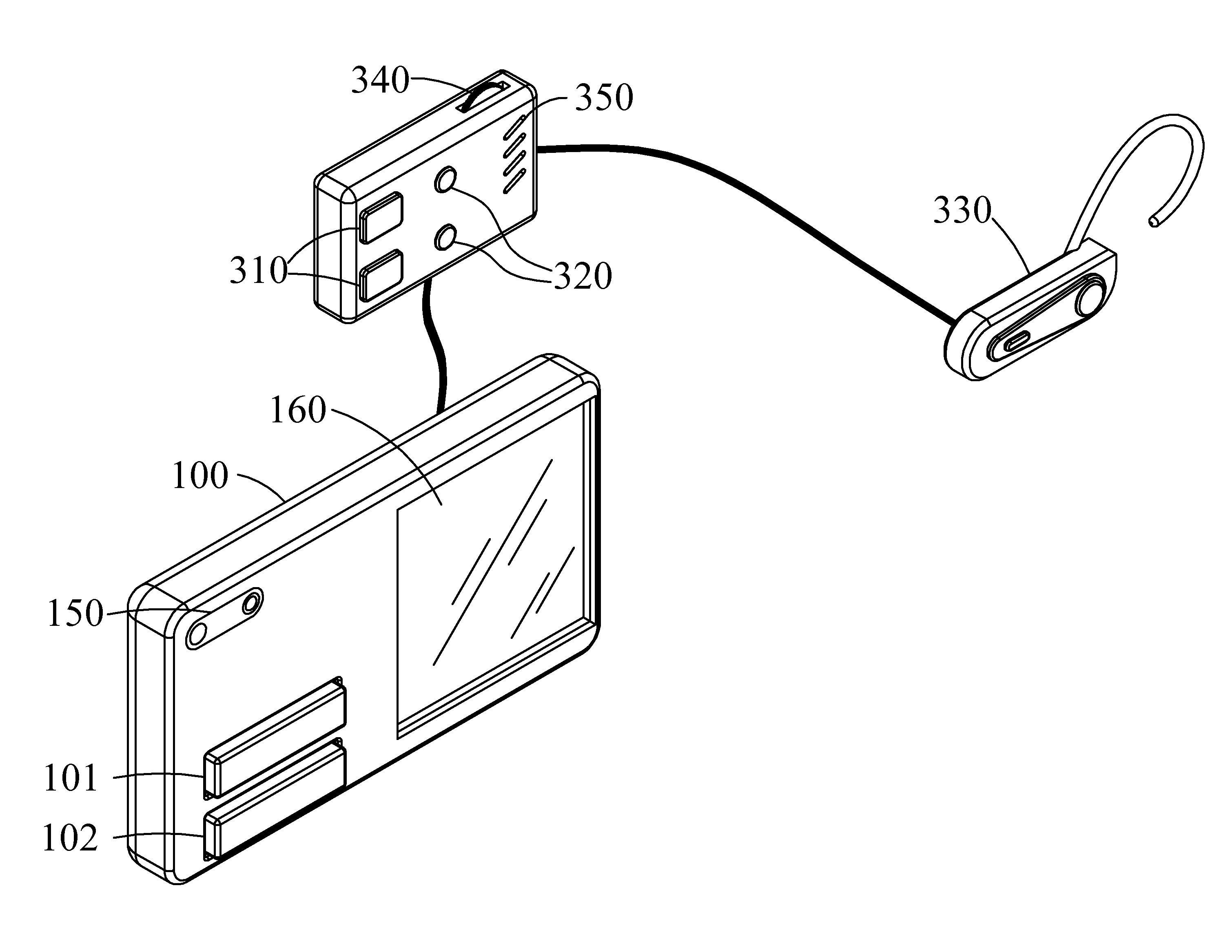
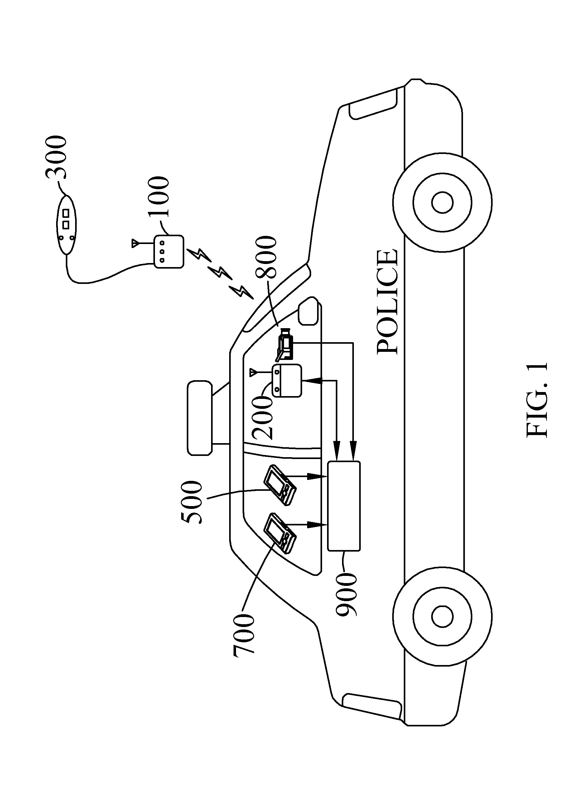
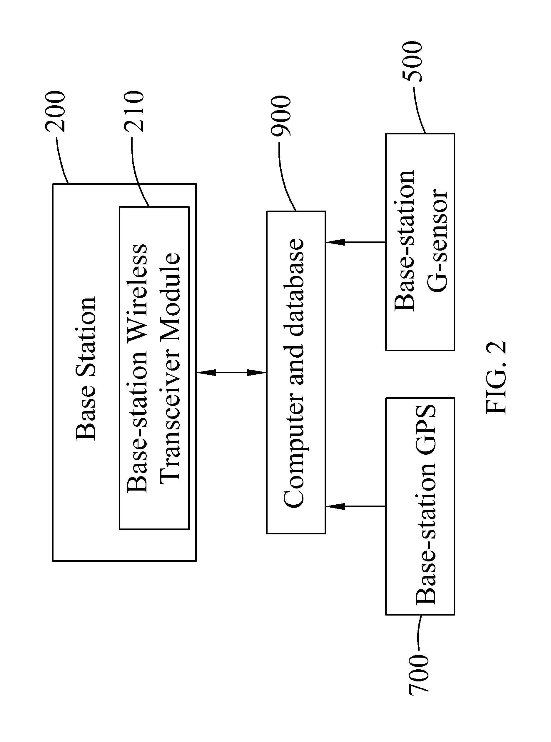
[0033]Please refer to FIG. 1 that schematically shows the use of a bidirectional microphone system of the present invention with a video recording system equipped on a police car or a fire engine. As shown, the bidirectional microphone system of the present invention comprises a wireless microphone 100, a base station 200, and an external control device 300. The present invention allows a bidirectional wireless transmission and communication between the wireless microphone 100 and the base station 200, and the external control device 300 may be connected to the wireless microphone 100 wirelessly or via a cable for controlling various operating functions of the wireless microphone 100 and displaying the different states of the operating functions of the wireless microphone 100. The base station 200 is disposed in, for example, a police car as shown in FIG. 1. The video recording system on the police car includes a base-station GPS 700, an in-car video system 800, and a computer and d...


PUM


Abstract

A bidirectional microphone system is disclosed, including a base station, a wireless microphone and an external control device. A bidirectional wireless communication may be performed between the wireless microphone and the base station. The external control device is connected to the wireless microphone for controlling the wireless microphone via at least one push button on the external control device. The external control device is also provided with light-emitting elements to show the function or status of the wireless microphone. The wireless microphone is provided with a global positioning system or a G-sensor for locating the coordinates of the wireless microphone under different situations. When the wireless microphone is in an emergency and located beyond the wireless communication range, the wireless microphone emits a high-power pulsed radio frequency signal for antenna of the base station to locate the position of the wireless microphone.

Description

CROSS-REFERENCE TO RELATED APPLICATION[0001]This application is a continuation-in-part of prior application Ser. No. 12 / 607,836, filed on Oct. 28, 2009. The patent application identified above is incorporated here by reference in its entirety to provide continuity of disclosure.FIELD OF THE INVENTION[0002]The present invention relates to a bidirectional microphone system, and more particularly to a wireless microphone operable via an external control device or a wireless microphone comprising a G-sensor and capable to emit a high-power pulsed radio frequency (RF) signal as a position indicator.BACKGROUND OF THE INVENTION[0003]It is very often policemen or firemen on duty get injured or attacked at criminal scene or accident site. To ensure the safety of policemen and firemen on duty, and to accurately record the original criminal scene to avoid any future dispute, the US Police has adopted the in-car video system for policemen to record the process of law enforcement for use as evid...

Claims


Application Information

Patent Timeline
Patent Type & Authority Patents(United States)
IPC IPC(8): H04B7/00G07C5/08H04M11/04H04R3/00
CPCG07C5/0866H04M11/04H04R3/005
Inventor CHANG, SHENG-HSIUNGCHANG, SHENG-YUAN
Owner TAIWAN GOMET TECH
Learn More