Leash and collar for animal control

a technology for animal control and collars, applied in the field of training, can solve the problems of inability to meet the needs of the average pet owner, the collars that are actuated by the owner often do not sufficiently coincidentally produce the stimulus of the misbehavior of the pet, and the standalone device that is not practical for the average pet owner

Inactive Publication Date: 2014-07-01
THALMANN STEPHEN DAVID
View PDF9 Cites 13 Cited by
  • Summary
  • Abstract
  • Description
  • Claims
  • Application Information

AI Technical Summary

Problems solved by technology

Dog owners frequently complain about pets that do not conform to a normal walking routine, but tend to run and tug at the leash in every direction, which diminishes the satisfaction of walking the dog.
A problem with the current state-of-the-art is that collars that are actuated by the owner often do not sufficiently coincidentally produce the stimulus to the misbehavior of the pet.
It is a standalone device that fails to be practical for the average pet owner because it does not associate the device with the dog's standard walking collar or harness.
Hultine et al (U.S. Pat. No. 6,116,192) provides an electrical impulse to the animal via a piezoelectric or mechanical sensing, but the leash is directly tied to the device that delivers the shock to the animal, thus either causing the animal to become averse to the standard collar and limiting where the trainer might want to apply the leash, as for example on harness.
In this instance the leash is again directly connected to the collar that supplies the shock to the animal, thus either causing the animal to become averse to the standard collar and limiting where the trainer might want to apply the leash, as for example on harness.
None of the prior art teaches a leash attachable to a normal dog collar or harness that is independent of a second collar that actually supplies an electrical or mechanical stimulation simultaneously with a tugging force.

Method used


Image

  • Leash and collar for animal control
  • Leash and collar for animal control
  • Leash and collar for animal control

Examples


Embodiment Construction

[0021]The following detailed description includes the best mode of carrying out the invention and is made for the purpose of illustrating the general principles of the invention and should not be taken in a limiting sense. The scope of the invention is determined by reference to the claims. Each part or function is assigned, even if structurally identical to another part, a unique reference number wherever that part is shown in the drawing figures.

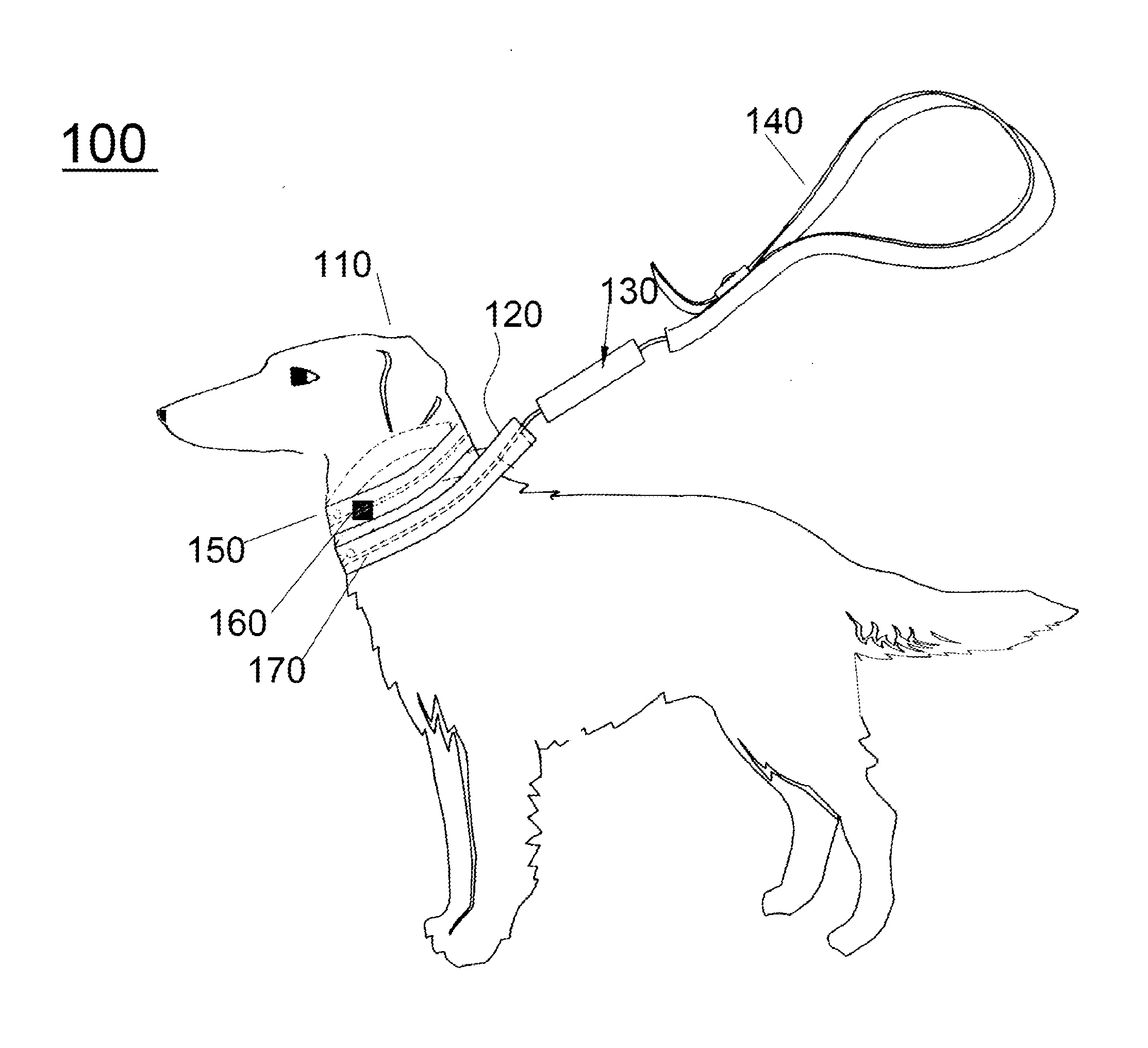
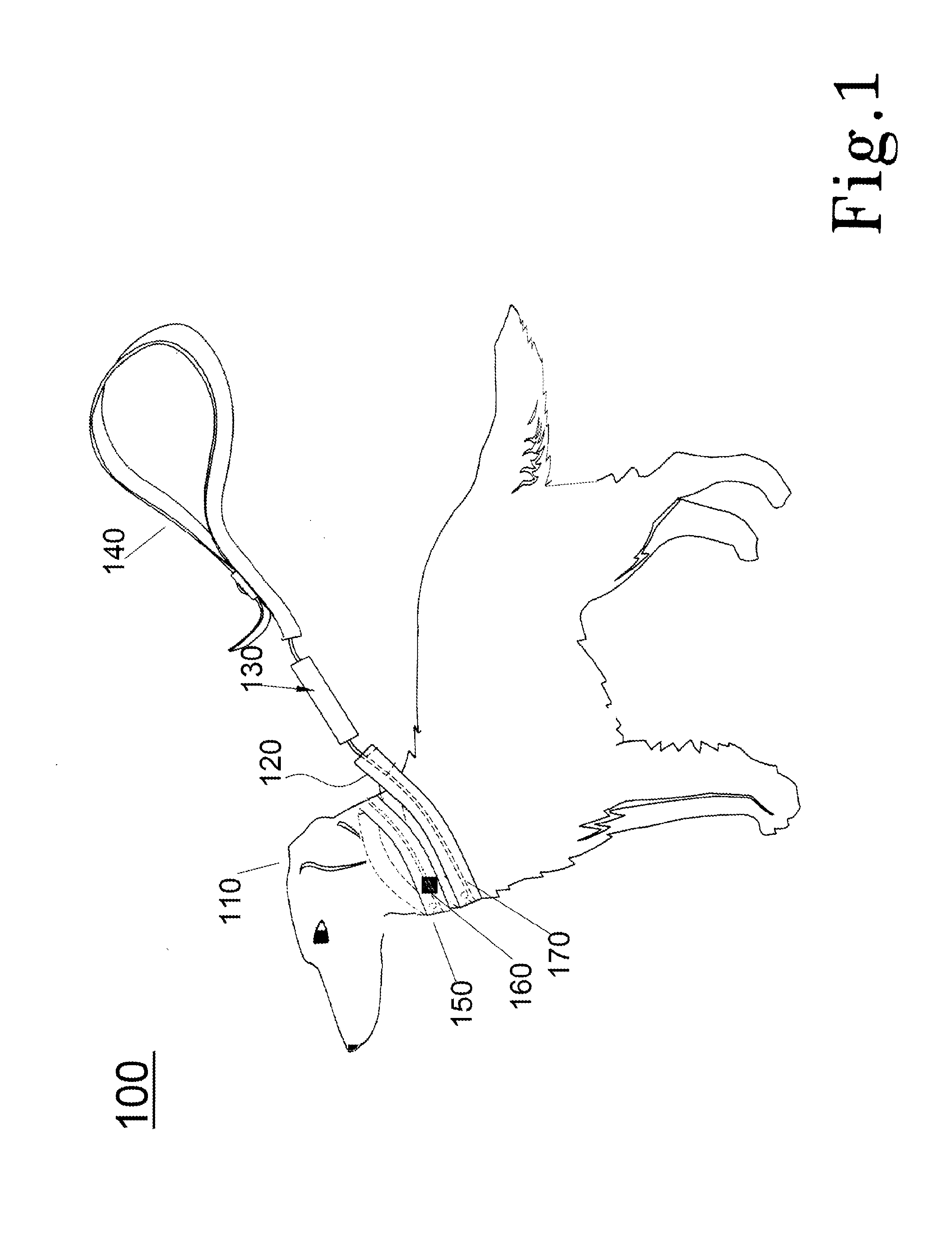
[0022]In the preferred embodiment, FIG. 1 shows the invention disclosed herein as it relates to an animal training system 100, which uses a leash 140 attached to a substantially rigid plastic or metal coupler device 130, which it turn is attached to a collar 170. When the coupler device 130 is subjected to a pulling force between an animal 110 and a trainer, a preset activation force triggers a transmitter that sends a signal to an independent correction collar 150. In another embodiment (not shown), it will be recognized that the coupler ...


PUM


Abstract

A leash held at one end by a trainer and attached at the other end to a coupler which attaches to either a harness or collar secured to the body of an animal, the coupler having therein an RF transmitter that transmits a signal consisting of one or more pulsed sequences dependent on the actuation of a switch that activates upon sensing a pulling force exerted between the animal and the trainer, said magnitude of force dependent on a spring, housed within the coupler and having an associated preset tension, wherein the RF transmitted signal is received by a receiver and a transducer located in an independent correction collar that transforms the received signal to a corresponding one or more applied electrical or mechanical pulsed forces to the bodily part of the of the animal secured by the correction collar.

Description

CROSS-REFERENCE TO RELATED APPLICATIONS[0001]This is a non provisional patent application claiming the priority benefit under 35 U.S.C. 119 (e) of U.S. Provisional Application No. 61 / 689,487, E-Z walk, no-tug leash to collar coupler filed on Jun. 7, 2012, the entire disclosures of which is hereby incorporated by reference.FIELD OF THE INVENTION[0002]This invention relates to training devices and systems utilizing leashes controllers, transducers and collars associated therewith to transmit signals and pressures to animals attached thereto.BACKGROUND OF THE INVENTION[0003]Dog owners frequently complain about pets that do not conform to a normal walking routine, but tend to run and tug at the leash in every direction, which diminishes the satisfaction of walking the dog. To reform the inclination of a dog to pull and run in scattered directions, training collars activated by handheld devices have been used to produce various stimulation that provide positive reinforcement for getting ...

Claims


Application Information

Patent Timeline
Patent Type & Authority Patents(United States)
IPC IPC(8): A01K27/00
CPCA01K27/009A01K15/029
Inventor THALMANN, STEPHEN, DAVID
Owner THALMANN STEPHEN DAVID
Why Eureka
Try Eureka