Agricultural implement with automatic down pressure control

a technology of automatic down pressure control and agricultural implements, applied in the field of agricultural row units, can solve the problems of difficult to maintain constant seed depth and other parameters, cumbersome changes in air pressure, and inability to adapt, and air bag systems typically do not allow for rapid change of force applied

Active Publication Date: 2014-07-01
DAWN EQUIPMENT COMPANY
View PDF338 Cites 71 Cited by
  • Summary
  • Abstract
  • Description
  • Claims
  • Application Information

AI Technical Summary

Problems solved by technology

As an agricultural planter row unit travels across fields with variable soil types, soil moisture, residue levels and topography, it is difficult to maintain constant seed depth and other parameters due to changing conditions which would ideally require varying the row unit down force pressure.
However due to the compressibility of air and the relatively large volumes required, changes in air pressure are very cumbersome and not adaptable to very fast change and response to in-cab controls on the go.
However, air bag systems typically do not allow for rapid change of the force being applied, because of the large volume of the air spring in relation to the cross section of the hose supplying the air.
Prior attempts to use devices such as combination spring / hydraulic shock absorbers do not provide ready adjustment on the go and tend to increase in force when rapidly striking a foreign object such as a rock requiring the row unit to quickly rise and come back down to resume planting.
This increase in force levels can cause damage to the planter row unit components.
However, with the accumulator separated from the force creating cylinder, pressure spikes can develop when hitting obstructions such as a rock at high speed since oil must be forced through hoses or tubes to the remotely located accumulator.
This is especially problematic on planters having 50 or more row units.
An air spring can allow for remote adjustment of the planter down pressure without stopping the forward motion of the implement, which is inefficient.
The slow rate at which an air spring system can be inflated or deflated means that even if a GPS system determines that a change needs to be made because of a programmed or sensed change in the local soil composition or conditions, by the time the pump can change the air pressure the implement has already moved too far forward of where the change needed to be made.

Method used


Image

  • Agricultural implement with automatic down pressure control
  • Agricultural implement with automatic down pressure control
  • Agricultural implement with automatic down pressure control

Examples


Embodiment Construction

[0023]Although the invention will be described in connection with certain preferred embodiments, it will be understood that the invention is not limited to those particular embodiments. On the contrary, the invention is intended to cover all alternatives, modifications, and equivalent arrangements as may be included within the spirit and scope of the invention as defined by the appended claims.

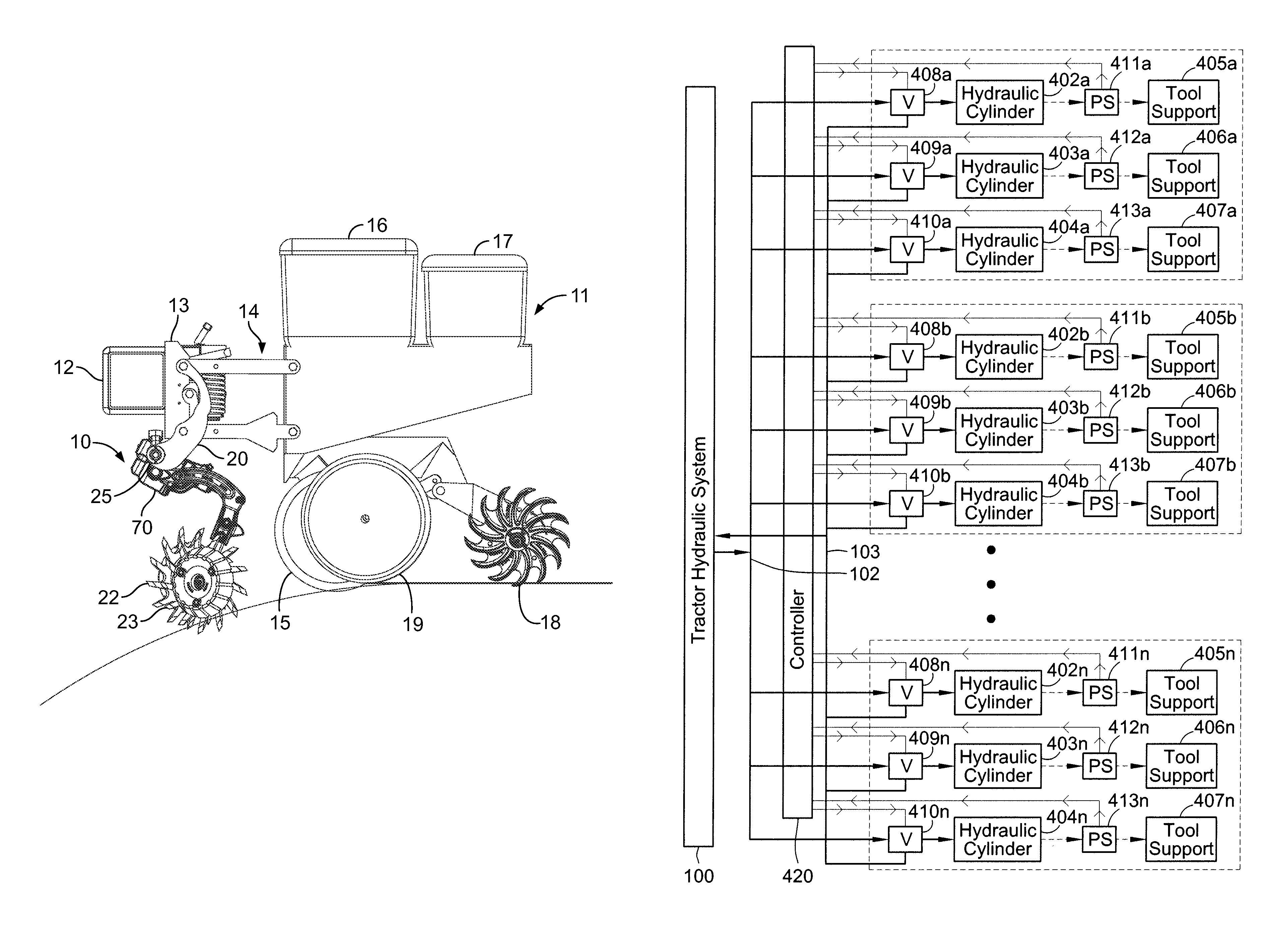
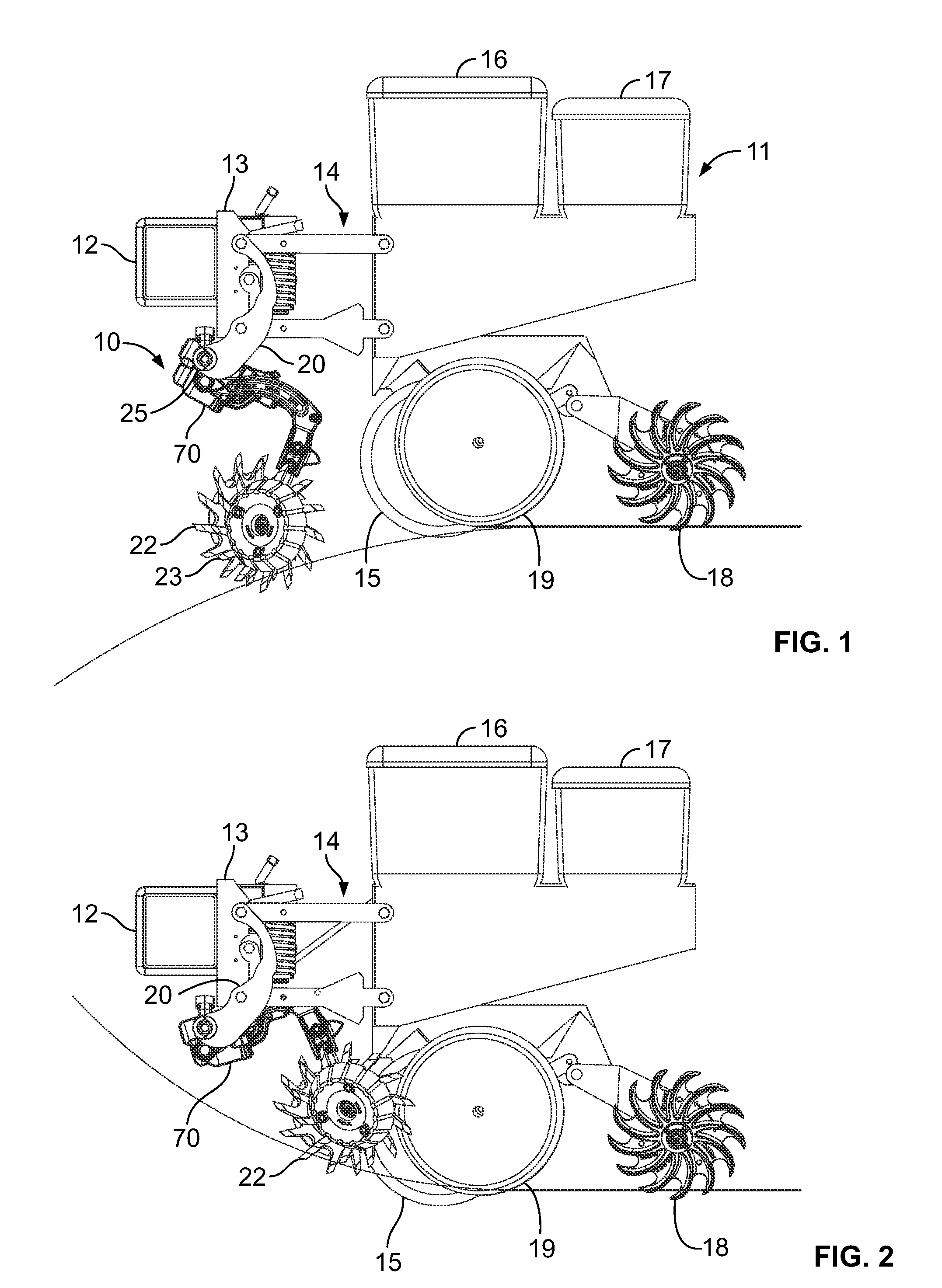
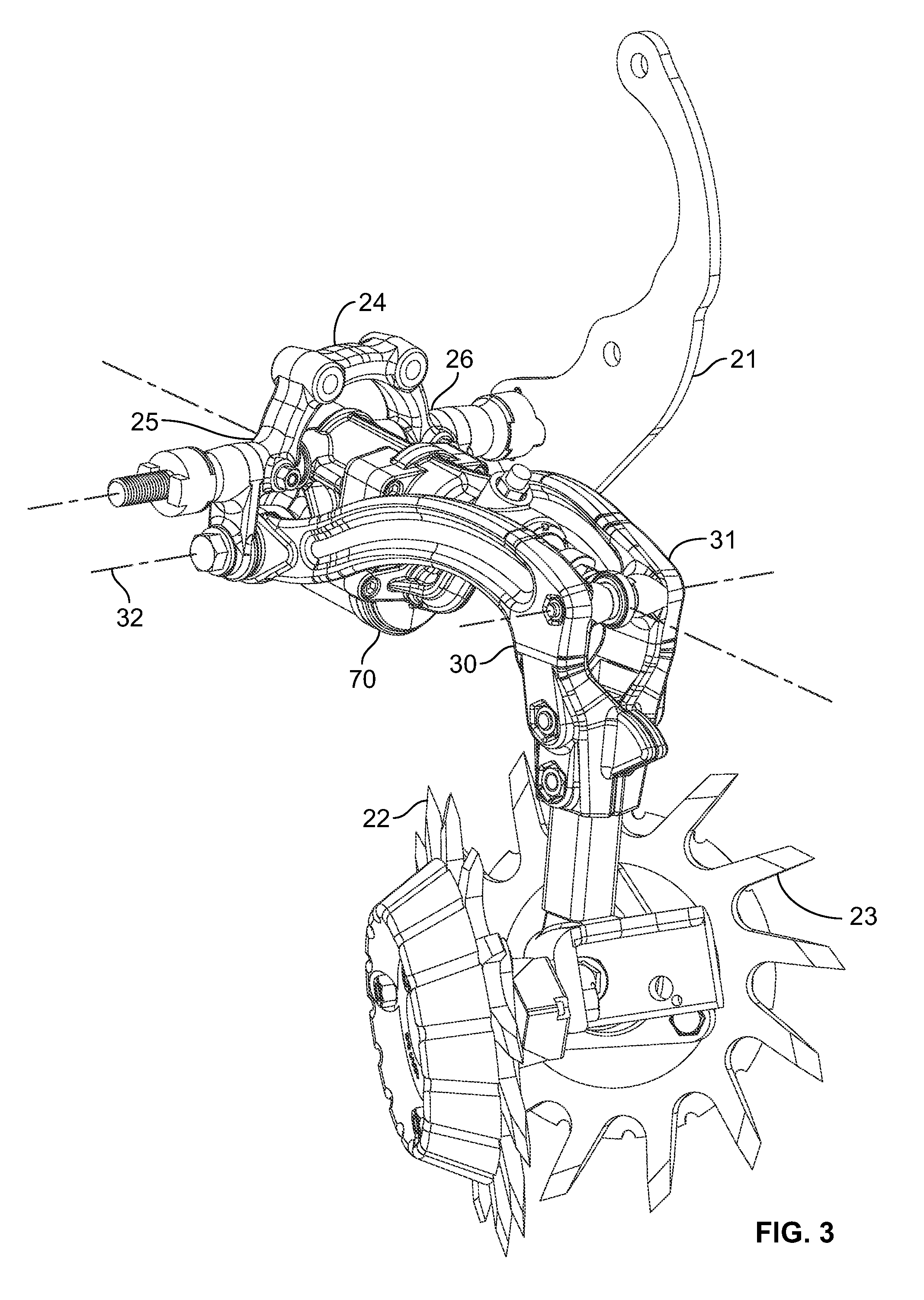
[0024]Turning now to the drawings, the illustrative implement includes a row-clearing unit 10 mounted in front of a planting row unit 11. A common elongated hollow towing frame 12 (typically hitched to a tractor by a draw bar) is rigidly attached to the front frame 13 of a four-bar linkage assembly 14 that is part of the row unit 11. The four-bar (sometimes referred to as “parallel-bar”) linkage assembly 14 is a conventional and well known linkage used in agricultural implements to permit the raising and lowering of tools attached thereto.

[0025]As the planting row unit 11 is advanced by the tr...


PUM


Abstract

An agricultural row unit includes a hydraulic cylinder coupled to a support member for urging a soil-engaging tool coupled to the support member downwardly toward the soil. A hydraulic line is coupled to the hydraulic cylinder for supplying pressurized hydraulic fluid to the cylinder, and a controllable valve is provided in the hydraulic line for controlling the supply of pressurized hydraulic fluid to the cylinder through the line. A pressure sensor, such as a load cell or strain gauge, is connected between the hydraulic cylinder and the support member for producing an electrical signal corresponding to the pressure on the tool, and a controller is coupled to the pressure sensor and the controllable valve, the controller being adapted to receive the electrical signal from the pressure sensor and produce a control signal for controlling the valve thus the supply of the hydraulic fluid to the cylinder.

Description

FIELD OF THE INVENTION[0001]The present invention relates to agricultural implements and, more particularly, to an agricultural row unit for use with agricultural implements such as planting row units.BACKGROUND OF THE INVENTION[0002]As an agricultural planter row unit travels across fields with variable soil types, soil moisture, residue levels and topography, it is difficult to maintain constant seed depth and other parameters due to changing conditions which would ideally require varying the row unit down force pressure. For example, farming with higher residue levels also requires higher row unit down force levels as row cleaners, coulters and other attachments require applied force to keep them in the ground and at consistent depths.[0003]At the same time, in many locations there are immovable rocks or other obstructions at or below the soil surface which require the planter row unit to be able to quickly and freely (without undue increase in the row unit down force) rise up an...

Claims


Application Information

Patent Timeline
Patent Type & Authority Patents(United States)
IPC IPC(8): A01B63/00A01B33/00
CPCA01C7/006A01C5/06A01C7/205Y02P60/20
Inventor BASSETT, JOSEPH, D.
Owner DAWN EQUIPMENT COMPANY
Why Eureka
Try Eureka