Determination of the effective lens position of an intraocular lens using aphakic refractive power

Active Publication Date: 2014-07-01
ALCON INC
View PDF287 Cites 14 Cited by
  • Summary
  • Abstract
  • Description
  • Claims
  • Application Information

AI Technical Summary

Problems solved by technology

If left untreated, cataracts can lead to blindness.

Method used


Image

  • Determination of the effective lens position of an intraocular lens using aphakic refractive power
  • Determination of the effective lens position of an intraocular lens using aphakic refractive power
  • Determination of the effective lens position of an intraocular lens using aphakic refractive power

Examples


Embodiment Construction

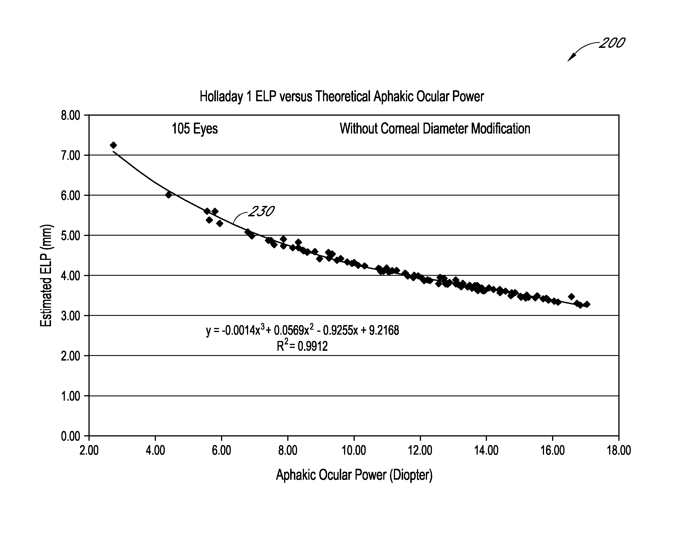
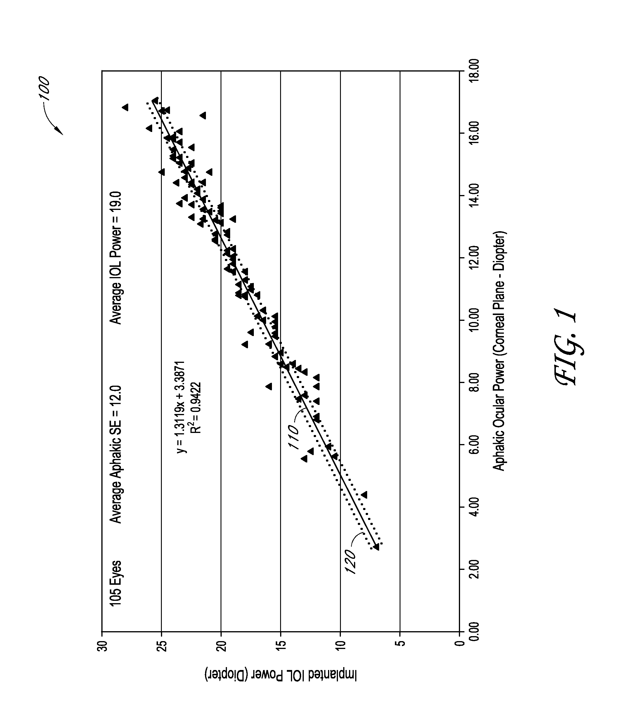
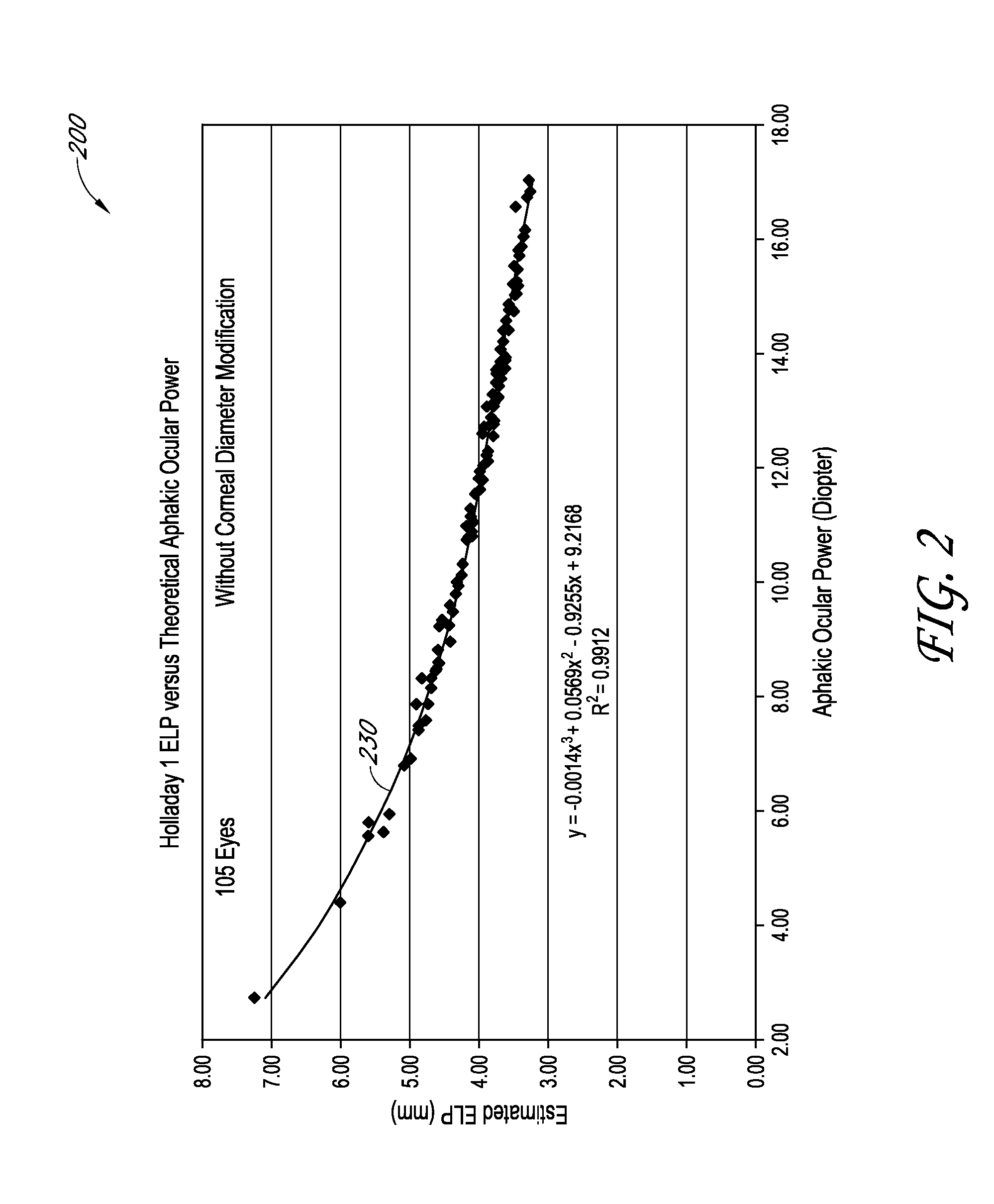
[0019]In a typical cataract surgery, a surgeon removes the natural crystalline lens from a patient's eye and an intraocular lens (IOL) is implanted in its place. By selecting an IOL having an appropriate amount of spherical and / or cylindrical power, an eye that prior to the surgery was, for example, myopic (near sighted), hyperopic (far sighted), and / or astigmatic can be restored to, for example, an emmetropic condition. The determination of an appropriate amount of IOL optical power for a given application is a significant aspect of obtaining satisfactory surgical outcomes for patients. Various factors can be considered when calculating the appropriate power for the IOL, such as 1) the axial length of the eye, for example, measured from the cornea to the retina; 2) the total optical power of the cornea, including its anterior and posterior surfaces; 3) the desired postoperative optical power (e.g., 0.0 diopters (D) of defocus for an emmetropic eye); and 4) the effective lens positi...


PUM


Abstract

An ophthalmic method for determining a relationship between aphakic ocular power and estimated effective lens position (ELP) of an intraocular lens (IOL) to be implanted in a patient's eye. The method can be used to determine an estimate of the ELP of an IOL given the aphakic ocular power of the patient's eye, for example, without measurement of the corneal curvature or axial length of the patient's eye. The estimate of ELP can then be used to determine a suitable value of optical power for the IOL to be implanted in the patient's eye.

Description

[0001]This application claims priority to U.S. Provisional Patent Application 61 / 225,532, filed Jul. 14, 2009, and entitled “DETERMINATION OF THE EFFECTIVE LENS POSITION OF AN INTRAOCULAR LENS USING APHAKIC REFRACTIVE POWER,” which is hereby incorporated by reference herein in its entirety.BACKGROUND OF THE INVENTION[0002]1. Field of the Invention[0003]The field of the invention relates to ophthalmic systems and procedures. In particular, the field of the invention relates to the determination of the post-surgical effective lens position (ELP) of an intraocular lens (IOL) and IOL power.[0004]2. Description of the Related Art[0005]Cataracts are clouded regions that can develop in the natural crystalline lens of an eye. A cataract can range in degree from slight clouding to complete opacity. Typically, formation of cataracts in human eyes is an age-related process. If left untreated, cataracts can lead to blindness. Surgeries have been developed for the treatment of cataracts by repla...

Claims


Application Information

Patent Timeline
Patent Type & Authority Patents(United States)
IPC IPC(8): A61F2/16G02C7/02
CPCG02C7/022A61F2/16G02C7/024A61F2/1662A61B3/0025A61B3/1015A61B3/10A61B3/103
Inventor PADRICK, THOMAS D.HOLLADAY, JACK T.
Owner ALCON INC
Why Eureka
Try Eureka