

Devices and methods of selecting intraocular lenses
a technology of intraocular lens and selection method, which is applied in the field of devices and methods for selecting intraocular lens, can solve the problems of not being able to apply the method
- Summary
- Abstract
- Description
- Claims
- Application Information
AI Technical Summary
Benefits of technology
Problems solved by technology
Method used
Image

Examples
example 2
Selecting Power of a Spherical IOL
[0065]The entrance pupil (on the first spectacle lens surface) is 5 mm in this example.
[0066]
E. CORNEASurfaceApex radius (mm)kanterior7.870.82posterior6.400.66
[0067]The radii apply at the center of the cornea. Corneal radius determined with a keratometer applies at a circle of about 3 mm diameter. With the k-values given, 7.90 mm and 6.42 mm, respectively, would have been measured.
[0068]
F. INTRAOCULAR LENSESG. PowerFront radiusBack radiusThicknessVault height(D)(mm)(mm)(mm)(mm)20.012.154−12.1541.100.0320.511.856−11.8561.110.0321.011.572−11.5721.120.02
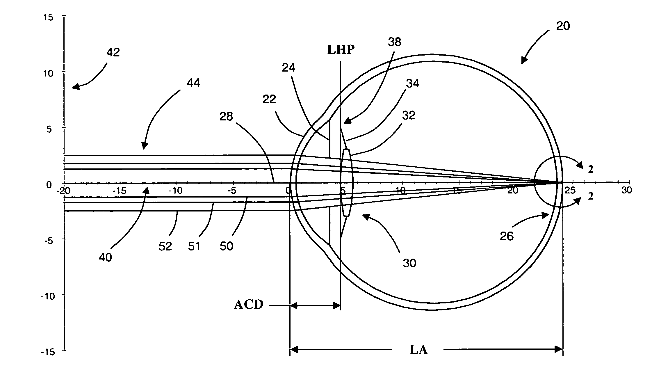
[0069]Vault height is the distance from LHP to the anterior surface of the lens (positive if the lens surface is posterior to LHP).
[0070]
H. AXIAL DISTANCESObjectSpectacle lensVertexCornealAxialdistancethicknessdistancethicknessLHPlength6 m2 mm12 mm0.574 mm4.36 mm23.92 mm
[0071]LHP was calculated by the formula
LHP=2.486+0.2174×(AL+ΔAL)−0.4213×CR
[0072]where CR is the measured corneal radius (7.90 mm), AL ...
example 3
Selecting Power of an Aspherical IOL
[0080]A generalized aspheric surface may be characterized using Equation (1), discussed in greater detail above herein. The entrance pupil (on the first spectacle lens surface) is 5 mm in this example.
[0081]
J. CORNEASurfaceApex radius (mm)kanterior7.870.82posterior6.400.66
[0082]The radii apply at the center of the cornea. Corneal radius determined with a keratometer applies at a circle of about 3 mm diameter. With the k-values given, 7.90 mm and 6.42 mm, respectively, would have been measured.
[0083]
K. INTRAOCULAR LENSESAnterior surfacePosterior surfaceVaultRadiusRadiusThicknessheightPower (D)(mm)k(mm)k(mm)(mm)20.012.154−7−12.154−71.130.0120.511.856−11.8561.130.0021.011.572−11.5721.140.0021.511.301−11.3011.15−0.0122.011.043−11.0431.16−0.01
[0084]Vault height is the distance from LHP to the anterior surface of the lens.
[0085]
L. AXIAL DISTANCESObjectSpectacle lensVertexCornealAxialdistancethicknessdistancethicknessLHPlength6 m2 mm12 mm0.574 mm4.36 mm2...
example 4
Demonstrating the Influence of k-Value
[0089]The entrance pupil (on the first spectacle lens surface) is 5 mm in this example.
[0090]The average k-value in the human population is 0.82, with a standard deviation of 0.18 (Dubbelman, M., Weeber, H. A., van der Heijde, G. L. and Völker-Dieben, H. J. Radius and asphericity of the posterior corneal surface determined by corrected Scheimpflug photography. Acta Ophthalmol Scand 2002; 80: 379-383).
[0091]For illustration a 20.5D spherical lens and a 21.5D aspherical lens with the following designs are chosen.
[0092]
N. INTRAOCULAR LENSESAnterior surfacePosterior surfaceVaultPowerRadiusa4a6Radiusa4a6Thicknessheight(D)(mm)k(mm−4)(mm−6)(mm)k(mm−4)(mm−6)(mm)(mm)20.511.856100−11.8561001.110.03spherical21.511.301−4−1 · 10−41 · 10−6−11.301−4001.15−0.01aspherical
[0093]Assume that the surgeon has come to these lens powers with a calculation method that does not take corneal asphericity into account. Which influence will variation of up to 3 standard devi...
PUM
 Abstract
Description
Claims
Application Information