
Dust collecting case and cutting machine equipped therewith

a technology for cutting machines and dust collectors, which is applied in the direction of boring/drilling components, metal-working machine components, manufacturing tools, etc., can solve the problems of cutting chips generated, difficult suctioning air in locations away from the suction port 103, and difficulty in suctioning and removing cutting chips, etc., to avoid interference with a cutting tool

Inactive Publication Date: 2014-07-01
ROLAND DG CORP
View PDF8 Cites 3 Cited by
  • Summary
  • Abstract
  • Description
  • Claims
  • Application Information

AI Technical Summary

Benefits of technology

The design enables full suction and removal of cutting chips from locations away from the suction port, ensuring efficient chip collection without tool interference, and allows for even air flow to enhance chip removal efficiency.

Problems solved by technology

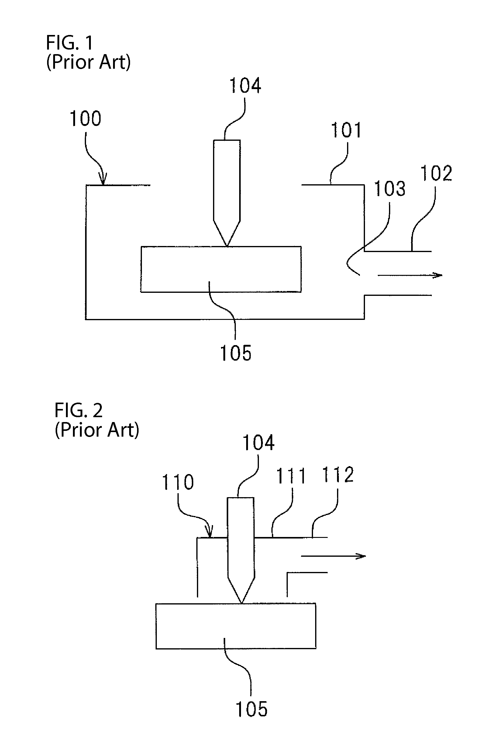
In cutting machines that cut work pieces with a rotating cutting tool, debris such as cutting chips are generated as a result of the cutting.
As a result, although suctioning air near a suction port 103 is relatively easy, suctioning air in locations away from the suction port 103 is more difficult.
This causes difficulty in suctioning and removing cutting chips when the tool 104 is in a location away from the suction port 103.

Method used


Image

  • Dust collecting case and cutting machine equipped therewith
  • Dust collecting case and cutting machine equipped therewith
  • Dust collecting case and cutting machine equipped therewith

Examples


Embodiment Construction

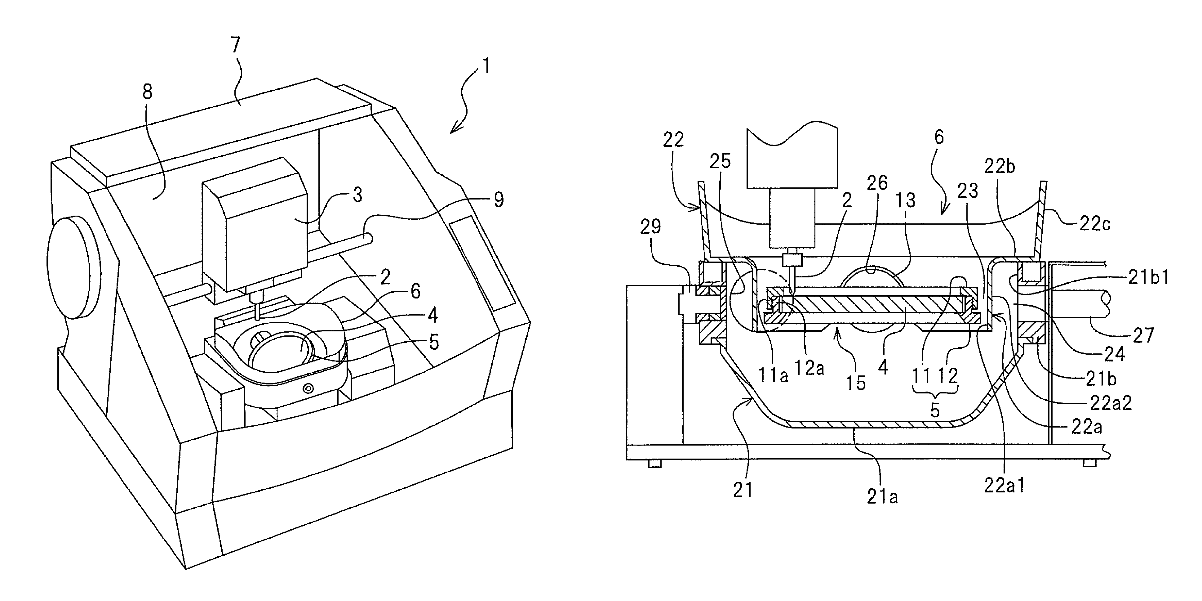
[0024]The present invention relates to a dust collecting case provided on a cutting machine for performing cutting work on a target object.

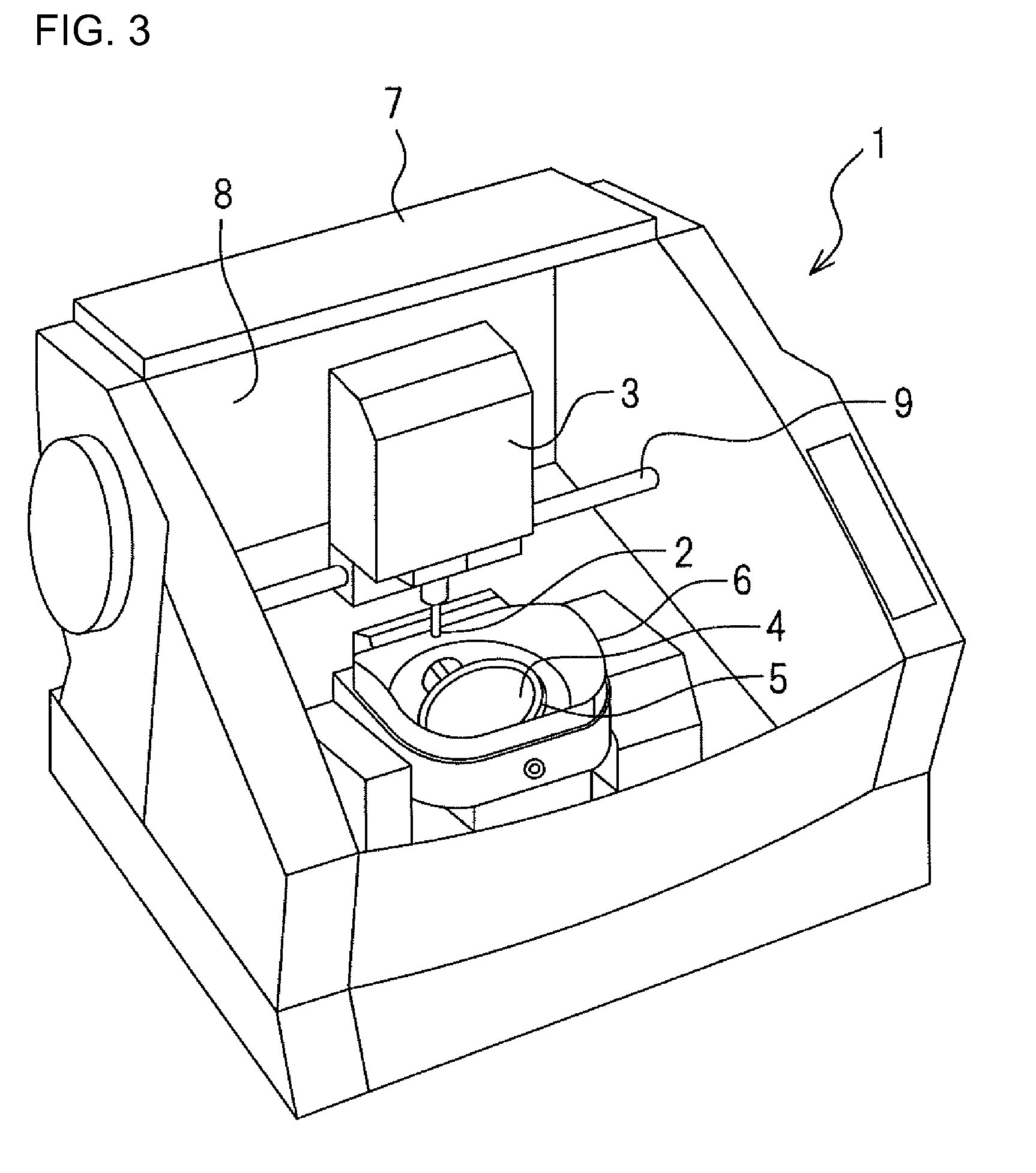
[0025]Referring to FIG. 3, a cutting machine 1 according to an embodiment of the invention is provided with a cutting tool (hereinafter “tool”) 2, a cutting head 3 for driving the cutting tool 2 and a holder 5 for holding a work piece 4. The work piece 4 represents an item to be cut by the cutting machine 1. The cutting machine 1 also includes a dust collecting case 6 covering bottom and side surfaces of the work piece 4 and the holder 5. A main body case 7 of the cutting machine 1 houses the cutting tool 2, the cutting head 3, the work piece 4, the holder 5, the dust collecting case 6 and other components of the cutting machine 1.

[0026]An opening 8 is formed on an upper side towards the front of the main body case 7. Although not shown, a clear cover may be provided on the main body case 7 to cover the opening 8. A user of the cutting machine 1 ...


PUM

PropertyMeasurementUnit
tubular shapeaaaaaaaaaa
sizeaaaaaaaaaa
shapeaaaaaaaaaa

Abstract

A dust collecting case provided on a cutting machine for cutting a target object includes an outer case member and an inner case member. The outer case member includes a bottom plate, a first side member extending from a peripheral edge of the bottom plate, and a suction port. The inner case member includes a second side member positioned inside the first side member, and an upper member provided between an upper portion of the first side member and an upper portion of the second side member such that the upper member closes from above a space surrounded by the first side member and the second side member. The second side member includes an inner peripheral surface that faces and surrounds an outer periphery of the target object. A gap is located in between an outer surface of the second side member and an inner surface of the first side member.

Description

CROSS-REFERENCE TO RELATED APPLICATIONS[0001]Pursuant to 35 U.S.C. §119(a), this application claims the benefit of earlier filing date and right of priority to Japanese Application No. 2010-213571, filed on Sep. 24, 2010, the contents of which are hereby incorporated by reference herein in its entirety.FIELD OF THE INVENTION[0002]The present invention relates to a dust collecting case provided on a cutting machine for performing cutting work on a target object.BACKGROUND OF THE INVENTION[0003]In cutting machines that cut work pieces with a rotating cutting tool, debris such as cutting chips are generated as a result of the cutting. Conventional cutting machines have been equipped with a dust collecting case and a dust collecting device for suctioning air inside the dust collecting case to suction and remove such cutting chips.[0004]FIGS. 1 and 2 are schematic diagrams showing configurations of conventional dust collecting cases. A dust collecting case 100 shown in FIG. 1 is provided...

Claims


Application Information

Patent Timeline
Patent Type & Authority Patents(United States)
IPC IPC(8): B23Q11/00B23Q1/54B23Q1/52
CPCB23Q1/525Y10T409/30896Y10T408/50B23Q1/5406B23Q11/0053B23Q11/0046Y10T409/308792Y10T409/307504Y10T409/304088
Inventor SUYAMA, AKIHIRO
Owner ROLAND DG CORP
Learn More