Color electrophotographic image forming apparatus
an electrophotographic and image forming technology, applied in the direction of electrographic process apparatus, instruments, optics, etc., can solve the problem of limited conditions for installing the main body of the apparatus, and achieve the effect of enhancing the operability of the jamming hole, and enhancing the degree of freedom of installation of the image forming apparatus
- Summary
- Abstract
- Description
- Claims
- Application Information
AI Technical Summary
Benefits of technology
Problems solved by technology
Method used
Image
Examples
first embodiment
[0042
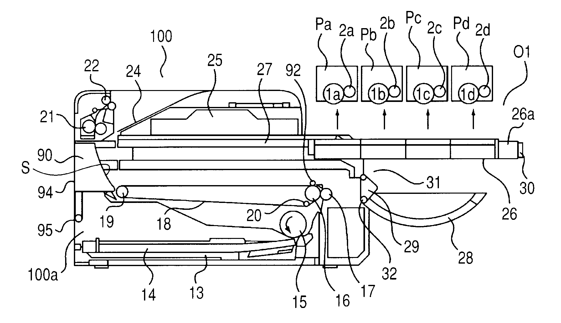
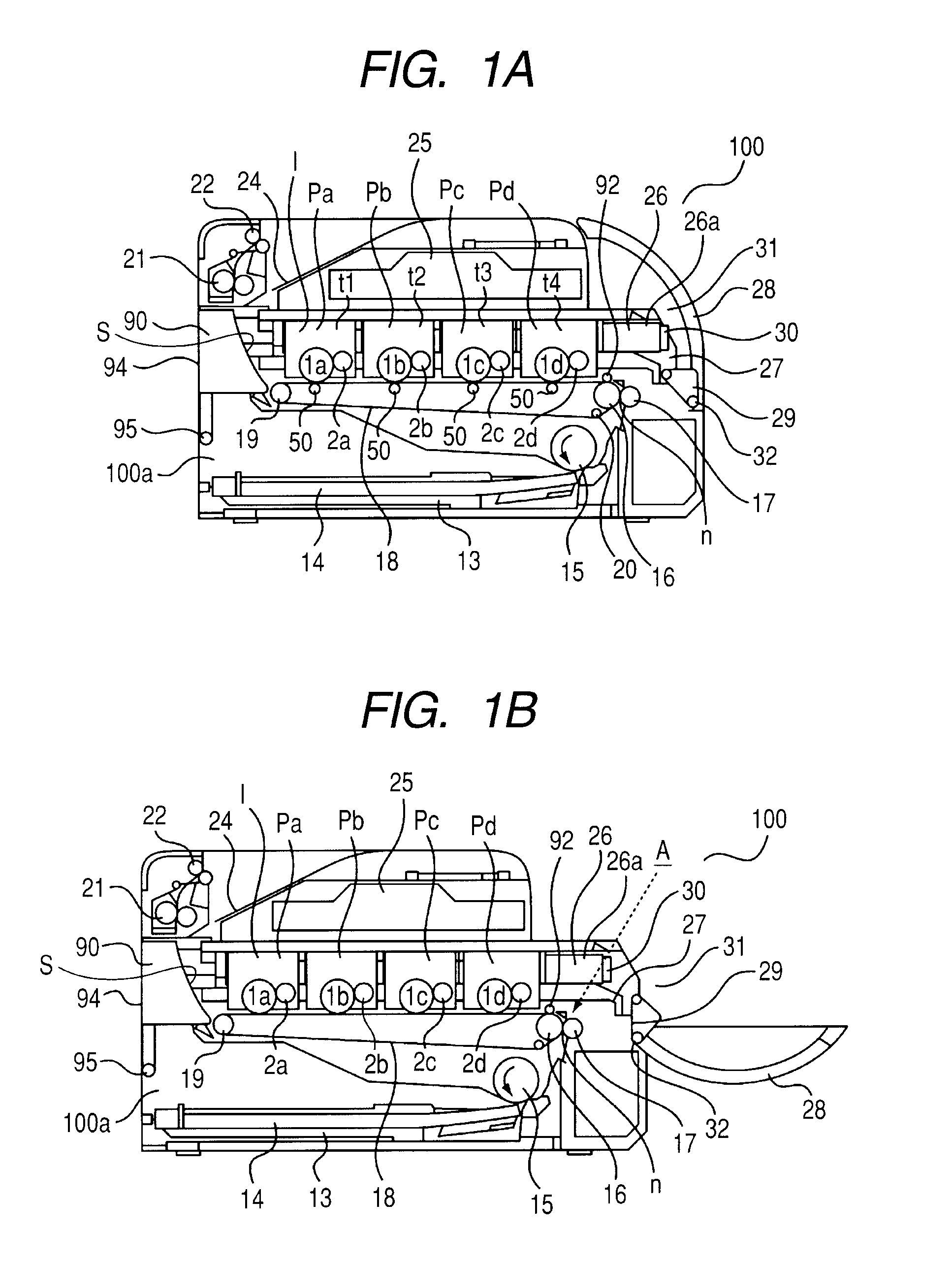
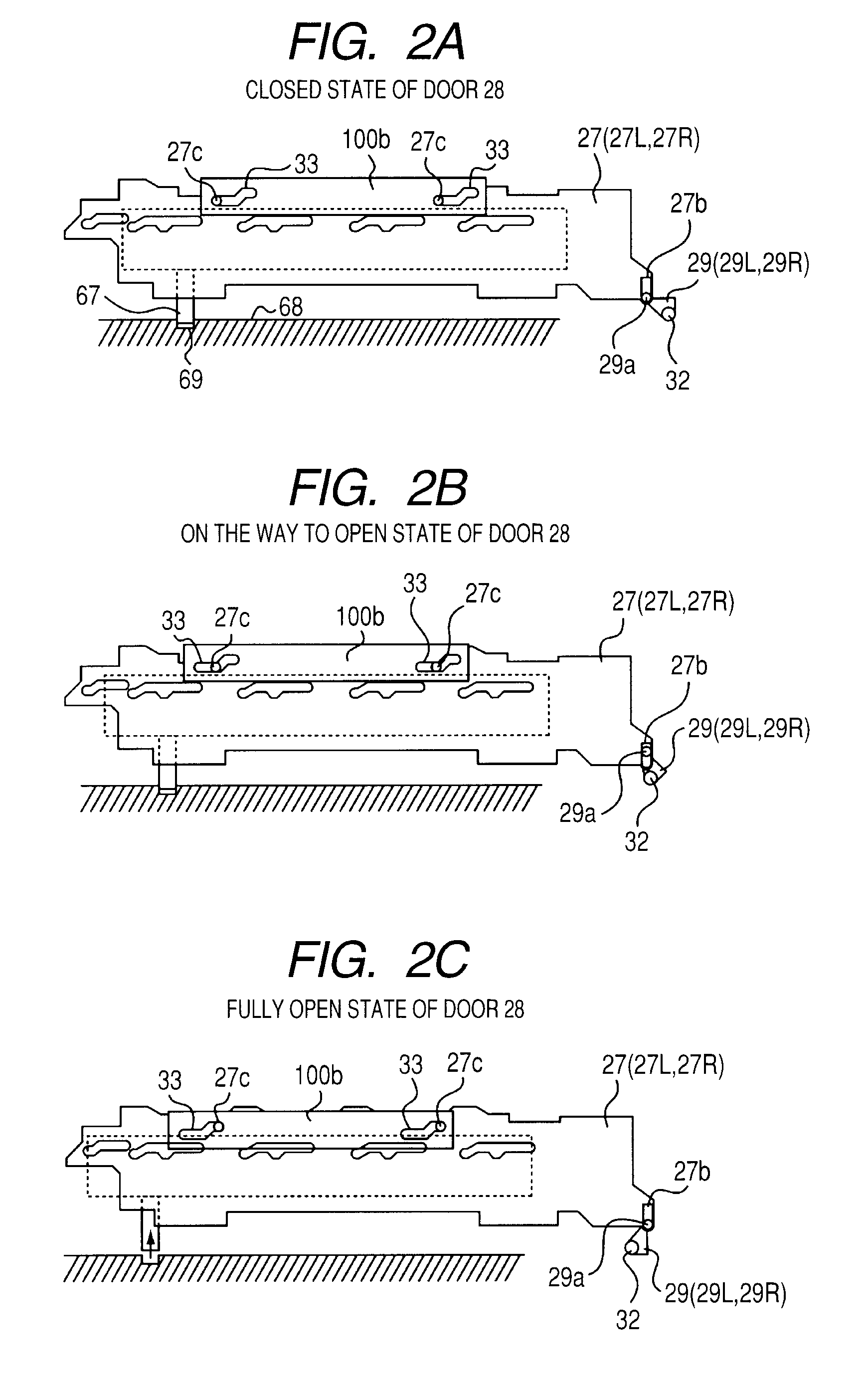
[0043]FIGS. 1A and 1B are cross-sectional illustrations of a laser printer, which being a color electrophotographic image forming apparatus according to a first embodiment of the present invention. Hereinafter, a description will be provided of a general structure and functions of the laser printer.
[0044]
[0045]First, referring to FIG. 1A, a description will be provided of a general structure of a color electrophotographic image forming apparatus according to a first embodiment of the present invention (hereinafter, referred to as an image forming apparatus). Note that, FIG. 1A is an explanatory sectional view of the image forming apparatus.
[0046]An image forming apparatus 100 of this embodiment is a full color laser printer using an electrophotographic process. Then, the image forming apparatus 100 forms an image on a recording medium (paper, OHP sheet, etc.) based on an image signal input from an external host apparatus (not shown) such as a personal computer, an image reader,...
second embodiment
[0092
[0093]Next, a description will be provided of an electrophotographic image forming apparatus according to a second embodiment of the present invention with reference to FIG. 11 to FIGS. 15A to 15C. It should be noted that the basic structure of this embodiment is the same with the above-mentioned embodiment, and hence duplicate description is omitted. Here, a description will be provided of characteristic structures of this embodiment. Further, for the members having the same functions as the above-mentioned embodiment, the same reference symbols are used.
[0094]In the first embodiment, in order that the tray 26 is removed from the opening portion 91, first, the door 28 is opened. Because of this, the link 29 is required to operate. This is because it is necessary to raise the tray 26 by operating the link 29, and to separate the photosensitive drums 1 from the conveyer belt 18.
[0095]Contrary to this, in this embodiment, when removing the tray 26 from the opening portion 91, the...
PUM
 Abstract
Description
Claims
Application Information
 - R&D
- Intellectual Property
- Life Sciences
- Materials
- Tech Scout
- Unparalleled Data Quality
- Higher Quality Content
- 60% Fewer Hallucinations
Browse by: Latest US Patents, China's latest patents, Technical Efficacy Thesaurus, Application Domain, Technology Topic, Popular Technical Reports.
© 2025 PatSnap. All rights reserved.Legal|Privacy policy|Modern Slavery Act Transparency Statement|Sitemap|About US| Contact US: help@patsnap.com


