
Printing device and method of controlling a printing device

a printing device and printing technology, applied in printing, other printing apparatus, etc., can solve the problems of large amount of fluid consumed by other printing operations, fluid ejection problems, forming or growing, etc., and achieve the effect of suppressing unnecessary fluid consumption

Active Publication Date: 2014-07-08
SEIKO EPSON CORP
View PDF4 Cites 0 Cited by
  • Summary
  • Abstract
  • Description
  • Claims
  • Application Information

AI Technical Summary

Benefits of technology

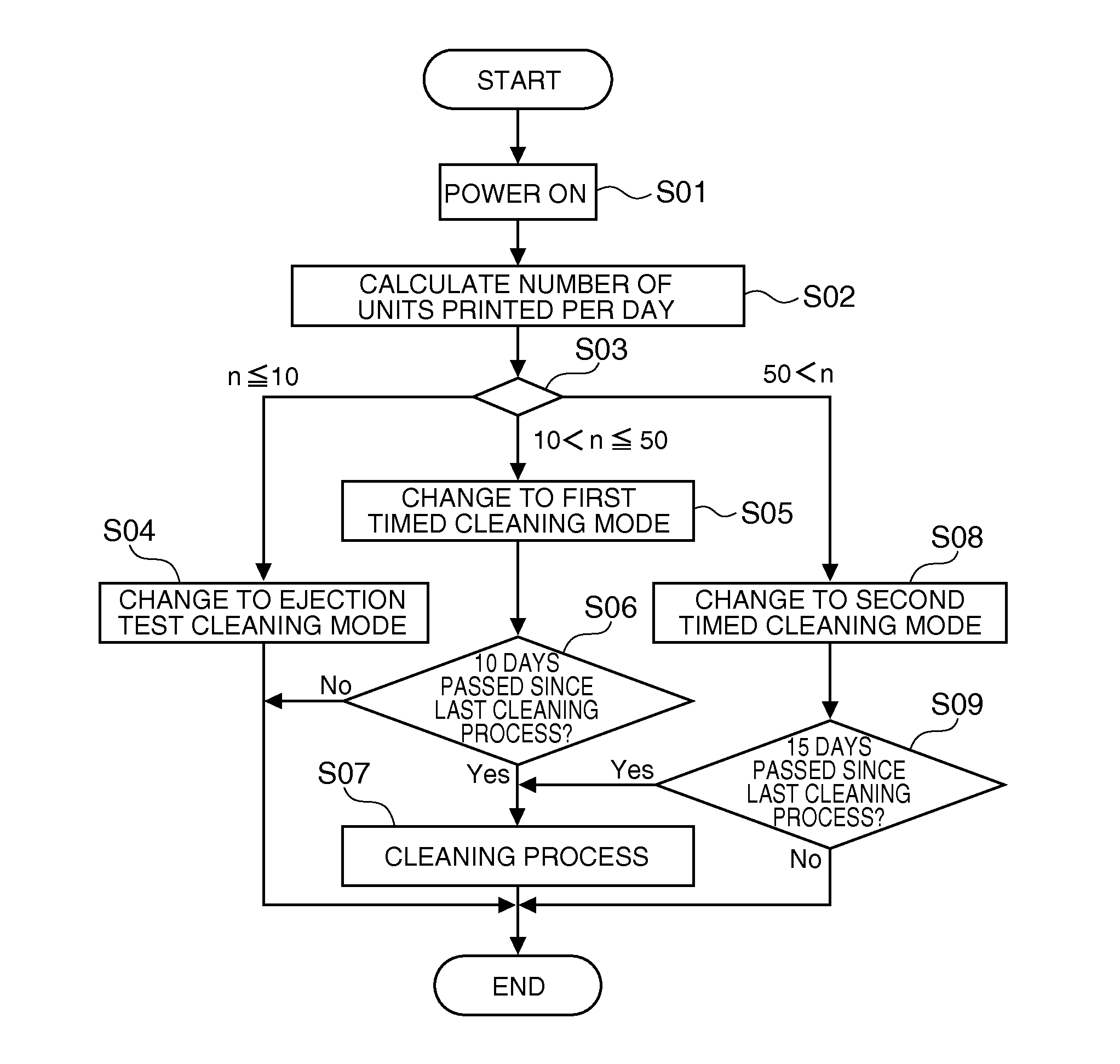
The invention provides a printing device and method for controlling it that can effectively clean the ejection head while reducing fluid consumption. The ejection test cleaning mode is designed to clean the nozzles after checking their ejection state, and the frequency of defective nozzles occurring depends on the operating condition of the print unit, so maintenance can be adjusted accordingly to suppress fluid consumption by operations other than printing. Additionally, the timed cleaning mode, which does not test ejection by the nozzles before cleaning, can help prevent excessive fluid consumption by unnecessary cleaning. The amount of fluid consumed during the ejection test is very small, so maintenance fluid consumption can be minimized.

Problems solved by technology

The recovery operation that restores the ejection performance of the ejection head by discharging fluid from the ejection head to the outside requires a specific amount of fluid, and a large amount of fluid may therefore be consumed by operations other than printing.
However, because the printer cannot check confirm the actual ejection status of the ejection head before performing the recovery operation, the recovery operation that discharges fluid from the ejection head may be performed even though there is no problem with the ejection head and the recovery operation is unnecessary.
When the operating condition is the operating time of the print unit, and the operating time in a specified period of time is long, cleaning is performed at a regular interval (timed cleaning mode) considering the high likelihood of bubbles, which can cause fluid ejection problems, forming or growing inside the ejection head.

Method used


Image

  • Printing device and method of controlling a printing device
  • Printing device and method of controlling a printing device
  • Printing device and method of controlling a printing device

Examples


Embodiment Construction

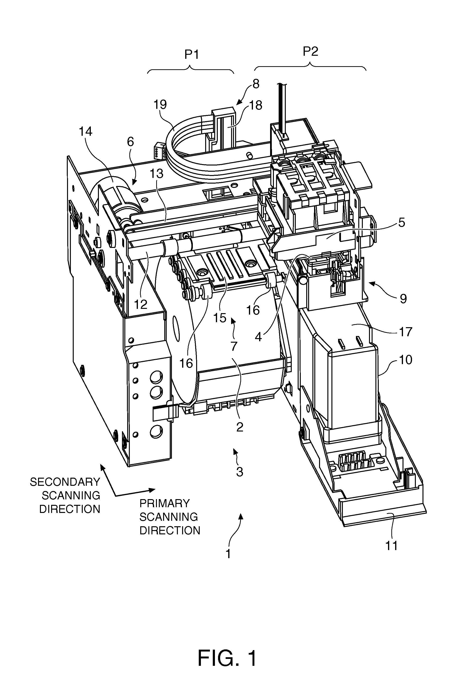
[0034]A printing device and a method of controlling a printing device according to a preferred embodiment of the invention is described below with reference to the accompanying figures. The printing device according to this embodiment of the invention repeatedly prints based on print data having unique information embedded in a specific format, such as in form printing, on roll paper used as the recording medium. This type of printing is referred to as “unit printing” below. This printing device has two modes including an ejection test cleaning mode that performs the ejection head cleaning process based on the results of an ejection test performed each time unit printing ends, and a timed cleaning mode that performs a cleaning process at regular times.

[0035]Note that herein the direction across the width of the roll paper used in the printing device is referred to as the primary scanning direction, and the length of the roll paper is the secondary scanning direction.

[0036]As shown i...


PUM


Abstract

A printing device has a print unit that ejects fluid from ejection nozzles and prints; an ejection test unit that checks if fluid is ejected from the ejection nozzles; a cleaning unit that performs a cleaning process in either a timed cleaning mode that performs a cleaning process at a predetermined interval, or an ejection test cleaning mode that performs a cleaning process based on a test result; a decision unit that determines whether to use the timed cleaning mode or the ejection test cleaning mode based on an operating condition of the print unit; and a mode changing unit that switches the mode between the timed cleaning mode and the ejection test cleaning mode according to the decision by the decision unit.

Description

BACKGROUND[0001]1. Technical Field[0002]The present invention relates to a printing device with an ejection head maintenance function, and to a method of controlling the printing device.[0003]2. Related Art[0004]Printing devices that have a recovery means for ejecting fluid in the ejection head to the outside to restore the fluid ejection performance of the ejection head, and control the recovery means according to how the user uses the printing device, are known from the literature. See, for example, Japanese Unexamined Patent Appl. Pub. JP-A-2009-066849. This printing device (printer) detects how frequently the power turns on / off, the print count, and the most frequent types of printing (monochrome or color printing) as indicators of how the user uses the printer, and based on the detected results changes the frequency of the recovery operation performed by the recovery means, and the type of fluid used in the recovery operation.[0005]The recovery operation that restores the eject...

Claims


Application Information

Patent Timeline
Patent Type & Authority Patents(United States)
IPC IPC(8): B41J2/165
CPCB41J2/16579B41J2/1652B41J2002/16573
Inventor HATAO, YOSUKE
Owner SEIKO EPSON CORP
Learn More