Fluid ejecting apparatus and method of controlling same

a technology of fluid ejection and fluid ejection, which is applied in the direction of printing, other printing apparatus, etc., can solve the problems of inability to smoothly eject the ink, unnecessary consumption of ink, and difficulty in predicting the change in the viscosity of ink, etc., to achieve excellent ejection state and suppress unnecessary fluid consumption

Inactive Publication Date: 2008-08-07
SEIKO EPSON CORP
View PDF9 Cites 0 Cited by
  • Summary
  • Abstract
  • Description
  • Claims
  • Application Information

AI Technical Summary

Benefits of technology

[0007]The present invention is contrived in consideration of the above-described situation. The object of the invention is to provide a fluid ejecting apparatus and a method of controlling a fluid ejecting apparatus capable of suppressing unnecessary consumption of fluid such as ink and maintaining an excellent ejection state.

Problems solved by technology

When a period of time during which ink is not ejected from the ejection nozzle becomes long, the viscosity of ink inside the record head increases, and accordingly, there is a possibility that a situation in which the ink cannot be smoothly ejected occurs.
However, when the operation for discharging ink is performed in a case where the viscosity of ink has not increased, the ink is consumed unnecessarily.
However, since the environment (temperature, humidity, and the like) under which the ink jet-type recording apparatus is used is not constant, it is difficult to predict the change in the viscosity of the ink.

Method used


Image

  • Fluid ejecting apparatus and method of controlling same
  • Fluid ejecting apparatus and method of controlling same
  • Fluid ejecting apparatus and method of controlling same

Examples


first embodiment

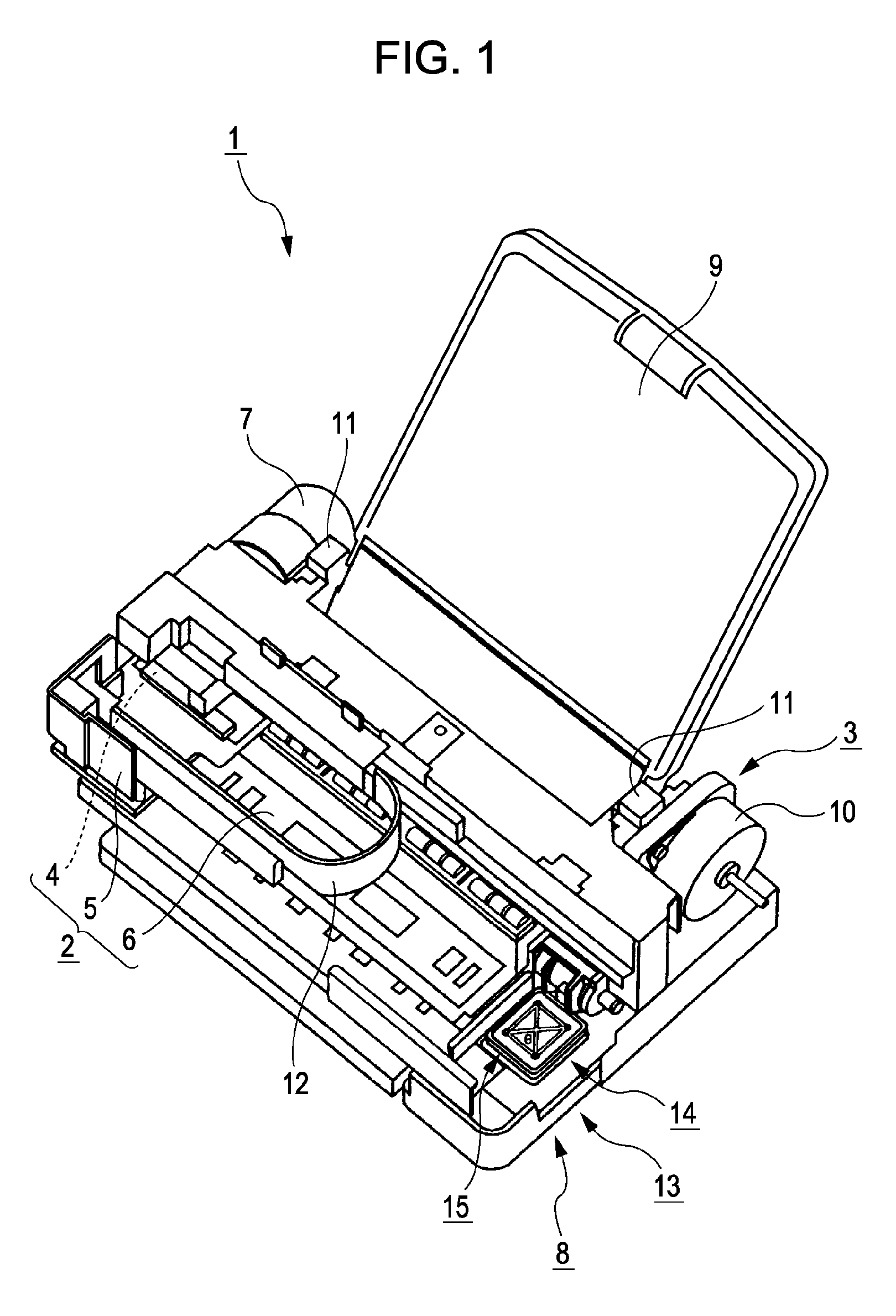
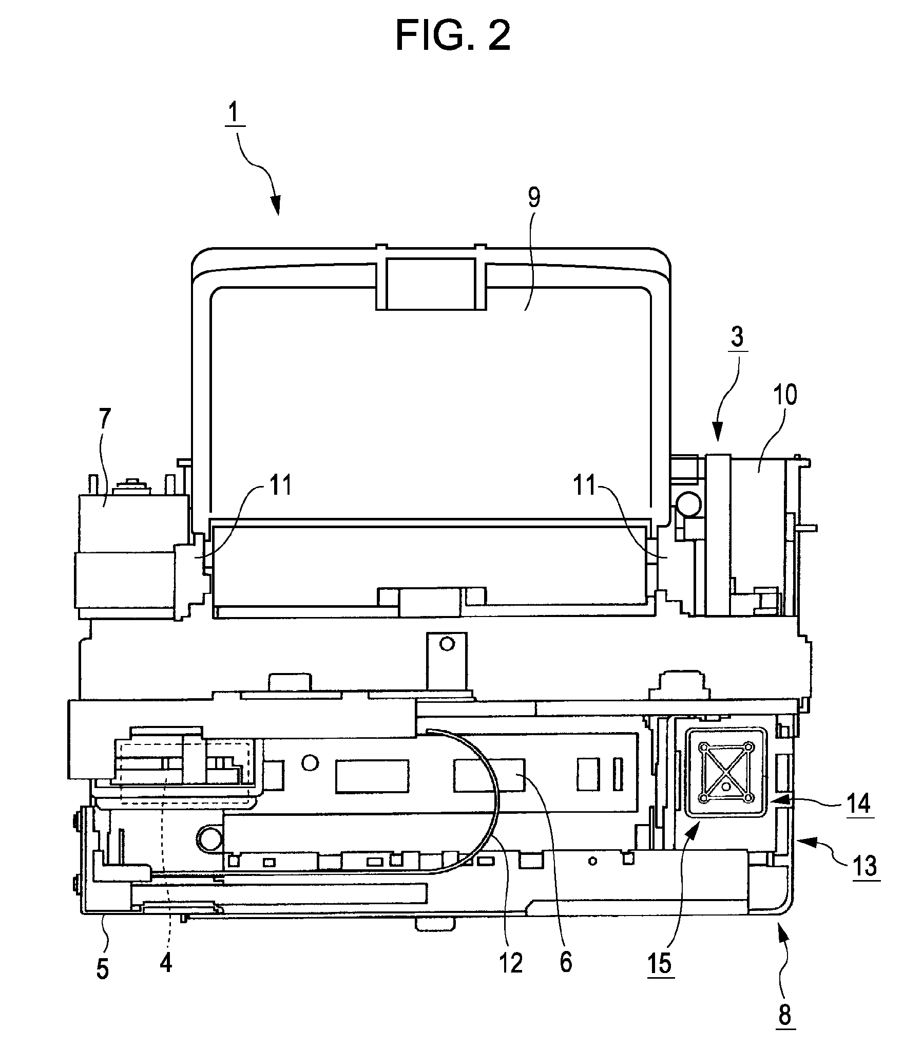
[0046]A first embodiment will now be described. FIG. 1 is a perspective view showing an example of a fluid ejecting apparatus according to the first embodiment. FIG. 2 is a plan view of the fluid ejecting apparatus. In this embodiment, a case where the fluid ejecting apparatus is a liquid ejecting apparatus that ejects liquid such as ink will be described as an example. In this embodiment, a case where the fluid ejecting apparatus is an ink jet-type recording apparatus that ejects ink onto a recording medium from an ejection nozzle of a record head and performs record for the recording medium will be described as an example. In this embodiment, as an example of the ink jet-type recording apparatus, an ink jet printer that performs record for a recording sheet by discharging (ejecting) ink droplets onto the recording sheet, which is a recording medium, will be described.

[0047]In FIGS. 1 and 2, the ink jet printer 1 includes a record unit 2 that performs record with ink for a recordin...

second embodiment

[0162]Next, a second embodiment will be described. In descriptions below, to a same or equivalent constituent portion as that of the above-described first embodiment, a same reference sign is attached, and a description thereof is simplified or omitted.

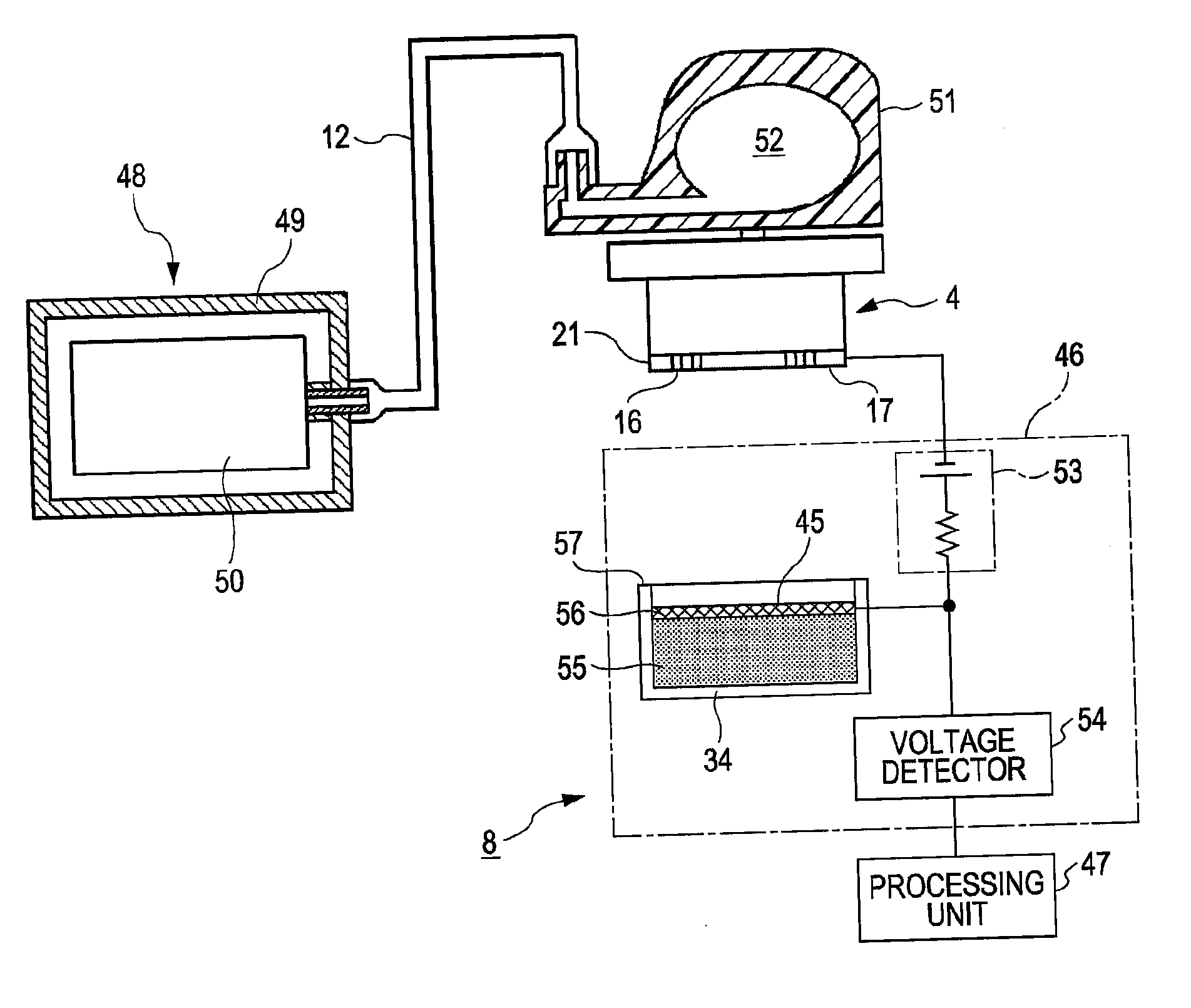
[0163]FIG. 15 is a flow chart for describing the operation of an ink jet printer 1 according to the second embodiment. A featured portion of this embodiment is that the ink jet printer 1 performs an operation (reference information acquiring operation) for acquiring a reference signal VPR on the basis of ink in the initial state, which is ejected from the ejection nozzle 16, in advance.

[0164]In this embodiment, for example, when an ink cartridge 48 is replaced with a new one, the reference information acquiring operation (Step SA0) is performed. The detection system 8 performs a detection operation by using ink of the ink cartridge 48 right after the replacement. Since the ink of the ink cartridge 48 right after the replacement can be...


PUM


Abstract

A fluid ejecting apparatus includes an ejection head having an ejection face formed with an ejection nozzle that ejects fluid, a detection device having a detector that is arranged to face the ejection face with a predetermined gap provided therebetween and to which the fluid is supplied from the ejection nozzle, the detection device outputting a detection signal in response to the fluid ejected from the ejection nozzle, and a processing unit that obtains information on the viscosity of the fluid on the basis of the detection signal.

Description

[0001]The entire disclosure of Japanese Patent Application No. 2007-028192, filed Feb. 7, 2007, is expressly incorporated by reference herein.BACKGROUND OF THE INVENTION[0002]1. Field of the Invention[0003]The present invention relates to a fluid ejecting apparatus and a method of controlling a fluid ejecting apparatus.[0004]2. Description of the Related Art[0005]As fluid ejecting apparatuses, ink jet-type recording apparatuses that eject ink onto a recording medium from an ejection nozzle of a record head have been known. When a period of time during which ink is not ejected from the ejection nozzle becomes long, the viscosity of ink inside the record head increases, and accordingly, there is a possibility that a situation in which the ink cannot be smoothly ejected occurs. Accordingly, an operation for regularly discharging ink from the ejection nozzle such as a flushing operation, a suction operation, or the like is performed (see JP-A-2006-123499).[0006]However, when the operati...

Claims


Application Information

Patent Timeline
Patent Type & Authority Applications(United States)
IPC IPC(8): B41J29/38B41J29/393B41J2/165
CPCB41J29/393B41J2/16579
Inventor TAKAHASHI, NOBUHITO
Owner SEIKO EPSON CORP
Why Eureka
Try Eureka