Illumination device capable of being controlled by blow

a technology of blowing and illumination device, which is applied in the direction of lighting and heating apparatus, semiconductor devices for light sources, instruments, etc., can solve the problems of inconvenient user, reduced life of electronic components within the illumination device, and user inability to switch on/off accordingly

Inactive Publication Date: 2014-07-08
DONGGUAN MASSTOP LIQUID CRYSTAL DISPLAY +1
View PDF3 Cites 1 Cited by
  • Summary
  • Abstract
  • Description
  • Claims
  • Application Information

AI Technical Summary

Benefits of technology

[0011]As mentioned in the above, the illumination device of the invention utilizes the blow sensing module to sense blow and controls the light emitting module to emit light in different brightness according to the number of blows sensed by the blow sensing module. Furthermore, the illumination device of the invention may be equipped with a cover made of ceramic material for the purpose of heat dissipation, such that the life of electronic components within the illumination device can increase. Moreover, the illumination device of the invention may be equipped with a power storage module so as to enable the illumination device to work normally during power failure.

Problems solved by technology

When both hands of a user are busy, the user cannot switch on / off the illumination device accordingly.
Furthermore, the heat dissipating area of a heat sink within the illumination device cannot increase due to appearance and space limitations, such that the life of electronic components within the illumination device may decrease due to accumulated heat.
Moreover, since the conventional illumination device cannot emit light during power failure, it is very inconvenient for the user.

Method used


Image

  • Illumination device capable of being controlled by blow
  • Illumination device capable of being controlled by blow
  • Illumination device capable of being controlled by blow

Examples


Embodiment Construction

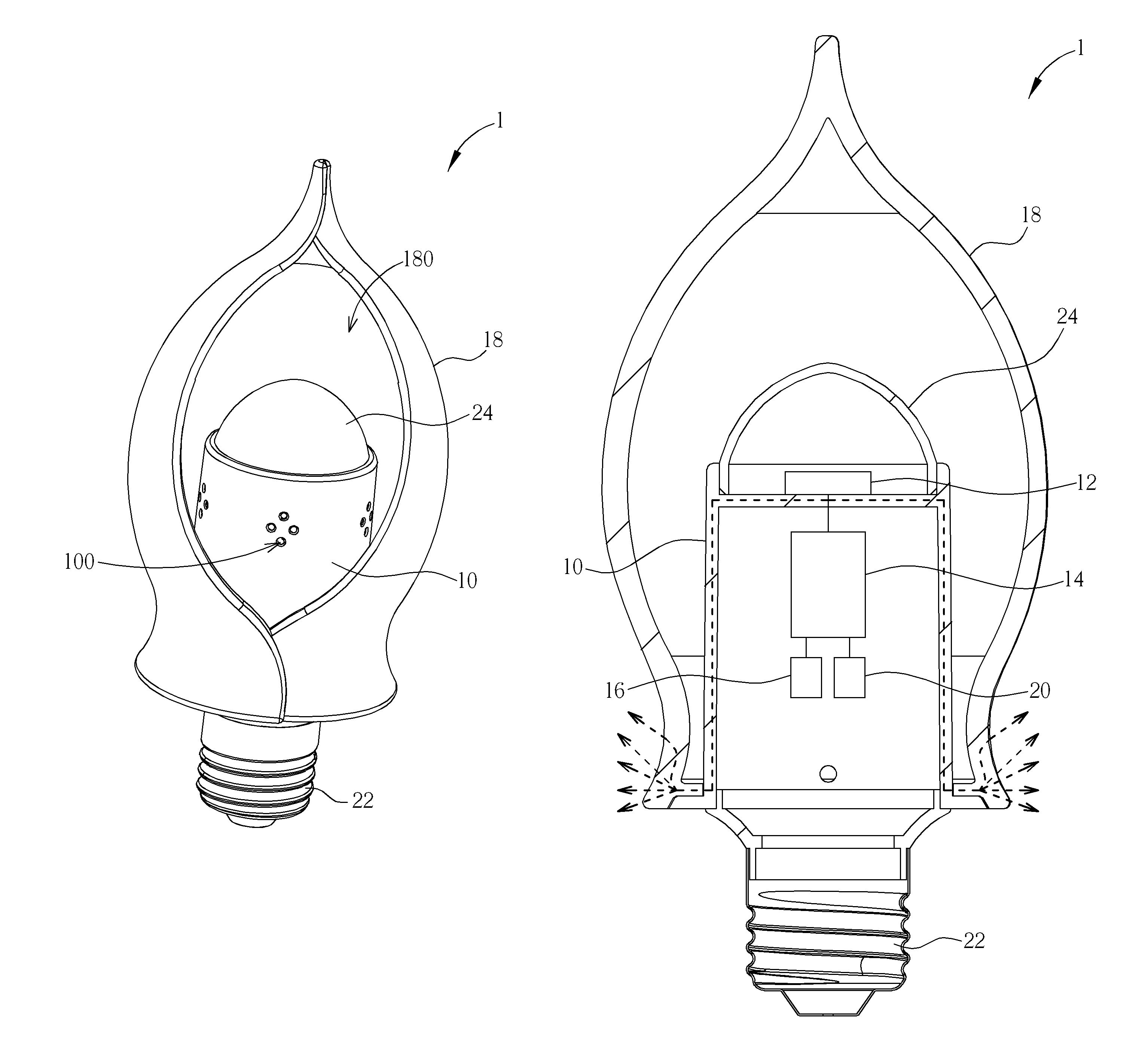
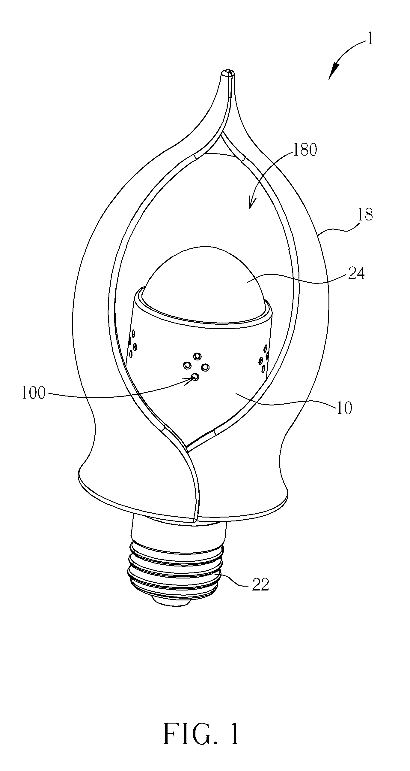
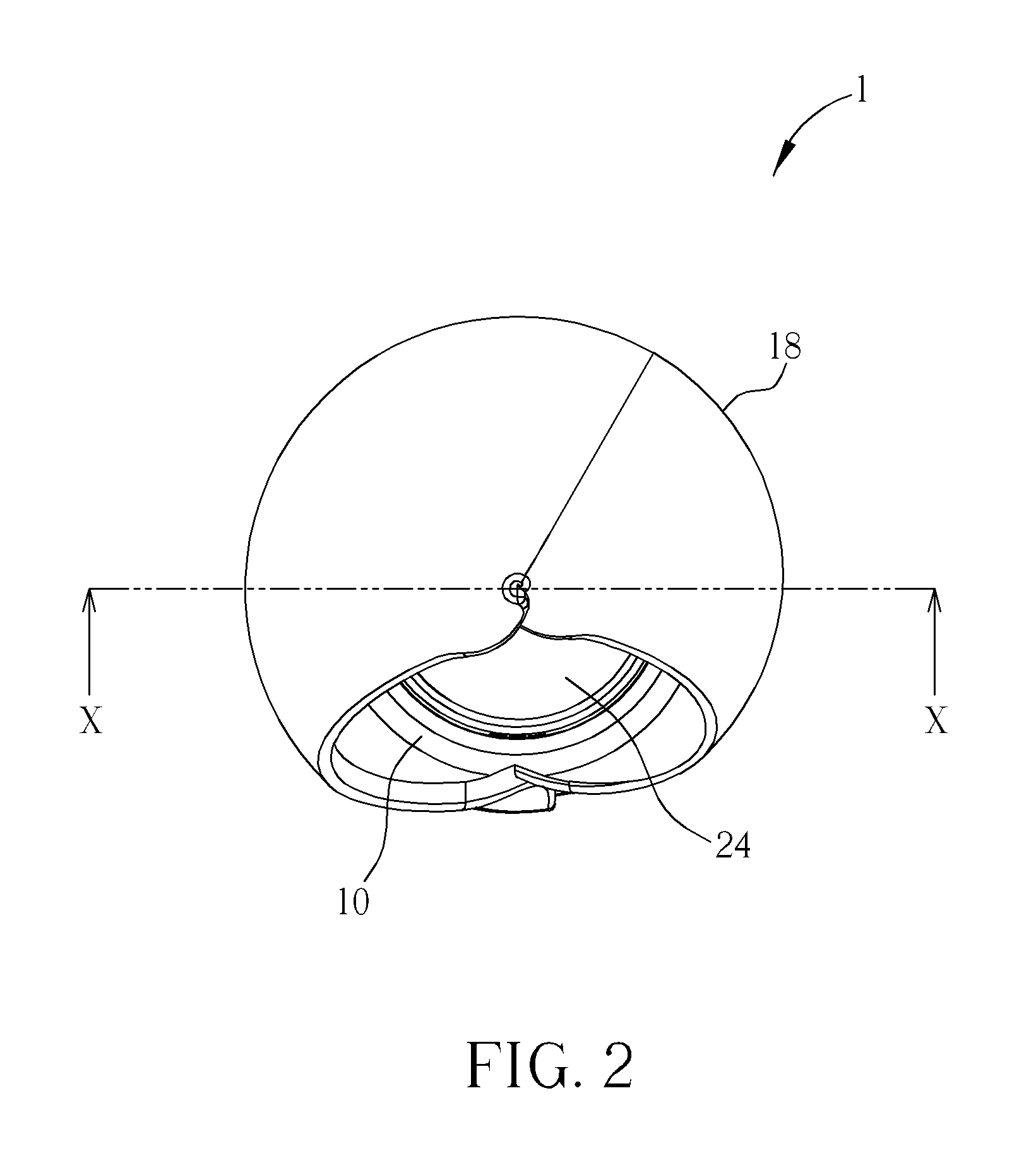
[0016]Referring to FIGS. 1 to 3, FIG. 1 is a perspective view illustrating an illumination device 1 capable of being controlled by blow according to one embodiment of the invention, FIG. 2 is a top view illustrating the illumination device 1 shown in FIG. 1, and FIG. 3 is a cross-sectional view illustrating the illumination device 1 along line X-X shown in FIG. 2. As shown in FIGS. 1 to 3, the illumination device 1 comprises a casing 10, a light emitting module 12, a driving circuit board 14, a blow sensing module 16, a cover 18, a power storage module 20, a lamp socket 22 and a lamp lens 24.

[0017]At least one air hole 100 is formed on a periphery of the casing 10. The number, position and shape of air holes 100 can be determined according to practical applications and are not limited to the embodiment shown in FIG. 1. The light emitting module 12 is disposed on a top of the casing 10. The lamp lens 24 is disposed on the casing 10 and covers light emitting module 12. In this embodim...


PUM


Abstract

An illumination device capable of being controlled by blow includes a casing, a light emitting module, a driving circuit board and a blow sensing module. At least one air hole is formed on a periphery of the casing. The light emitting module is disposed on a top of the casing. The driving circuit board is disposed in the casing and electrically connected to the light emitting module. The blow sensing module is disposed in the casing, electrically connected to the driving circuit board and used for sensing blow through the at least one air hole. The driving circuit board controls the light emitting module to emit light in different brightness according to a number of blows sensed by the blow sensing module.

Description

BACKGROUND OF THE INVENTION[0001]1. Field of the Invention[0002]The invention relates to an illumination device and, more particularly, to an illumination device capable of being controlled by blow.[0003]2. Description of the Prior Art[0004]So far an illumination device is considered a necessity by a lot of people. In general, the illumination device can be switched on / off by pressing a corresponding button switch or a remote controller manually. When both hands of a user are busy, the user cannot switch on / off the illumination device accordingly. Furthermore, the heat dissipating area of a heat sink within the illumination device cannot increase due to appearance and space limitations, such that the life of electronic components within the illumination device may decrease due to accumulated heat. Moreover, since the conventional illumination device cannot emit light during power failure, it is very inconvenient for the user.SUMMARY OF THE INVENTION[0005]An objective of the inventio...

Claims


Application Information

Patent Timeline
Patent Type & Authority Patents(United States)
IPC IPC(8): F21L19/00
CPCH05B37/0227F21K9/13F21V3/005F21V3/02F21V3/04F21V23/0471F21V23/0485F21Y2101/02F21V29/506F21K9/23F21Y2115/10H05B47/115Y02B20/40
Inventor YE, ZHI-TINGCHEN, CHIN-LIANGLIN, MING-CHUANCHEN, TSUNG-WEN
Owner DONGGUAN MASSTOP LIQUID CRYSTAL DISPLAY
Why Eureka
Try Eureka