Position detection system

a detection system and position technology, applied in the field of position detection system, can solve the problems of limiting the electric power supplied to the magnetic-field generating circuit, reducing the size of the capsule medical device, and difficult to produce a capsule medical device that is easily swallowed by the subject, so as to reduce the amount of work required for detecting the position and so on. , the effect of reducing the amount of work

Inactive Publication Date: 2012-04-24
OLYMPUS CORP
View PDF7 Cites 1 Cited by
  • Summary
  • Abstract
  • Description
  • Claims
  • Application Information

AI Technical Summary

Benefits of technology

[0010]The above-mentioned Patent Document 1 discloses a position detection technique for a capsule medical device using a capsule medical device provided with a magnetic-field generating circuit including an LC resonant circuit connected to an AC power source and a detection device that is disposed outside the capsule medical device and that detects the magnetic field generated by the magnetic-field generating circuit. According to this technique, the magnetic-field generating circuit generates an externally directed magnetic field on the basis of the AC electric power supplied from the AC power source. In this way, the detection device can detect the position of the capsule medical device by detecting the magnetic field.
[0011]However, according to the above-described technique for position detection, a magnetic-field generating circuit including an LC resonant circuit connected to an AC power source is disposed inside the capsule medical device. Therefore, it is difficult to reduce the size of the capsule medical device, and thus, there is a problem in that it is difficult to produce a capsule medical device having a size that is easily swallowed by the subject. In contrast, if the size of the capsule medical device is reduced, the size of the AC power source is also reduced, thus limiting the electric power supplied to the magnetic-field generating circuit. Consequently, the intensity of the magnetic field generated by the magnetic-field generating circuit is reduced, and thus there is a problem in that position detection of the capsule medical device becomes more difficult. There is also a problem in that, since the life of the AC power source is shortened, the life of the capsule medical device is also shorted.

Problems solved by technology

Therefore, it is difficult to reduce the size of the capsule medical device, and thus, there is a problem in that it is difficult to produce a capsule medical device having a size that is easily swallowed by the subject.
In contrast, if the size of the capsule medical device is reduced, the size of the AC power source is also reduced, thus limiting the electric power supplied to the magnetic-field generating circuit.
Consequently, the intensity of the magnetic field generated by the magnetic-field generating circuit is reduced, and thus there is a problem in that position detection of the capsule medical device becomes more difficult.
There is also a problem in that, since the life of the AC power source is shortened, the life of the capsule medical device is also shorted.

Method used


Image

  • Position detection system
  • Position detection system
  • Position detection system

Examples


first embodiment

[0124]A position detection system according to a first embodiment of the present invention will be described below with reference to FIGS. 1 to 10.

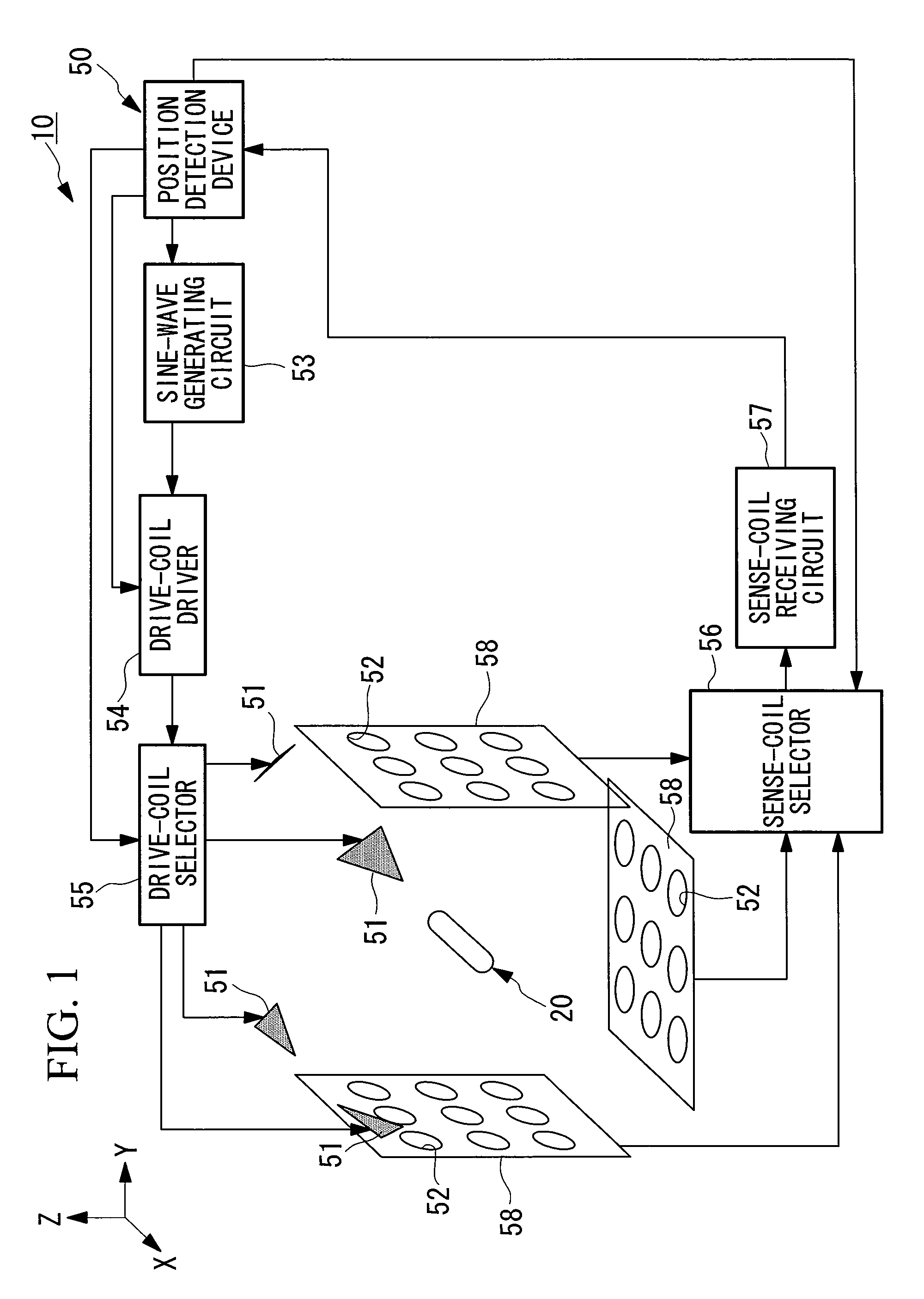
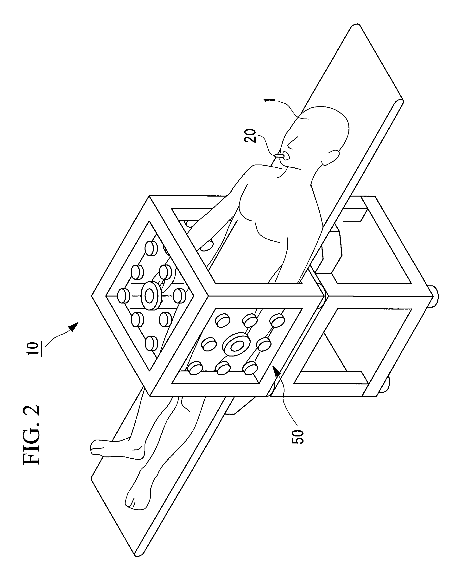
[0125]FIG. 1 is a schematic view illustrating the overall structure of a position detection system according to this embodiment. FIG. 2 is a perspective view illustrating the exterior of the position detection system shown in FIG. 1.

[0126]As shown in FIGS. 1 and 2, a position detection system 10 is mainly formed of a capsule endoscope (device, capsule medical device) 20, which is a capsule medical device introduced into a body cavity of a subject 1, per oral or per anus, to optically image an internal surface of a passage in the body cavity and wirelessly transmit an image signal, and a position detection device (amplitude-component detection means, position analyzing section) 50 that detects the position of the capsule endoscope 20. The capsule medical device is not limited to the above-described capsule endoscope; instead, it may be a c...

second embodiment

[0182]Next, a second embodiment of the present invention will be described with reference to FIGS. 11 to 13.

[0183]The basic structure of a position detection system according to this embodiment is the same as that according to the first embodiment, except that the structure of the position detection device differs from that according to the first embodiment. Therefore, in this embodiment, only the position detection device and its periphery will be described with reference to FIGS. 11 to 13, and a description of the capsule endoscope and so on will be omitted here.

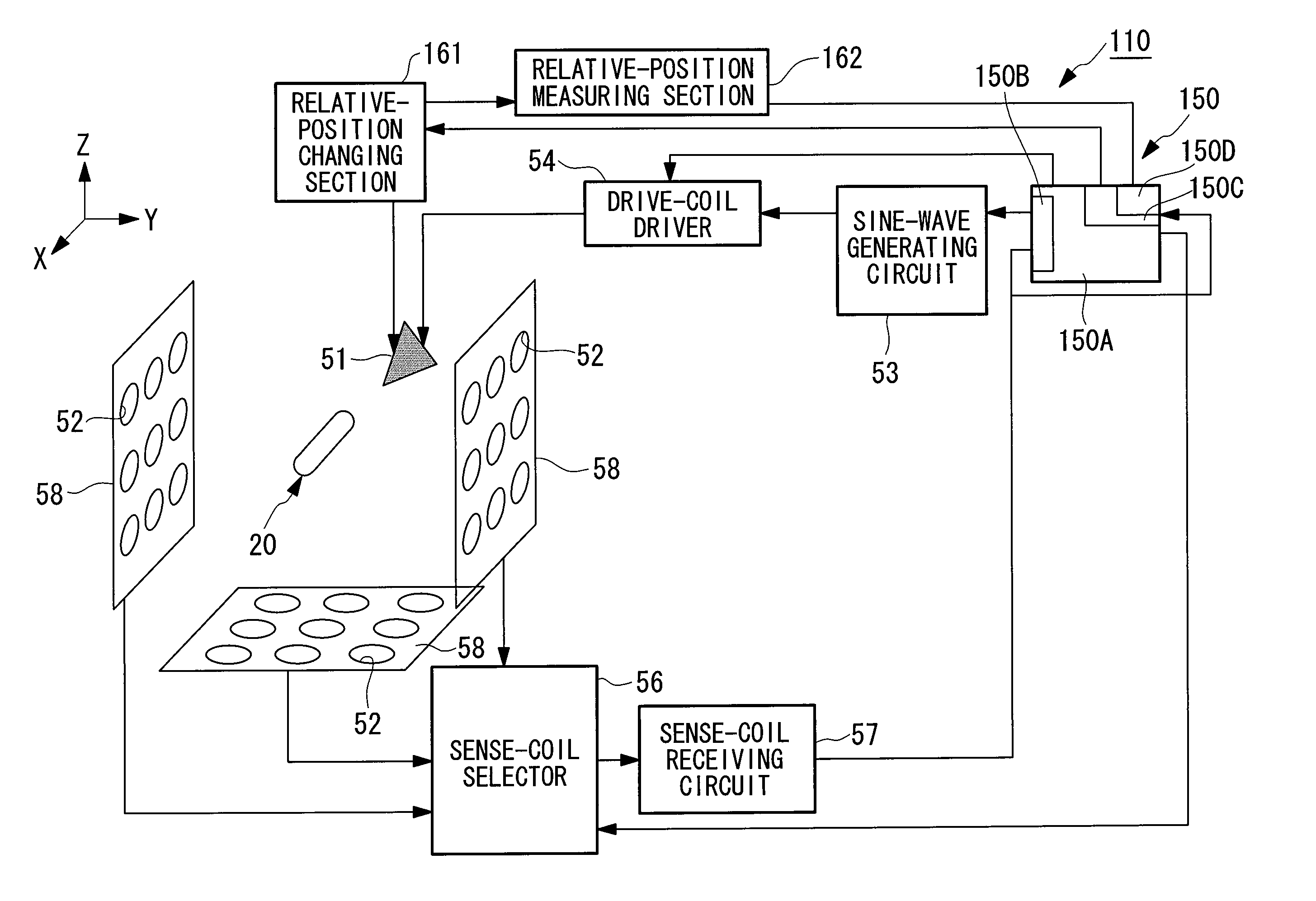
[0184]FIG. 11 is a block diagram illustrating, in outline, the position detection system according to this embodiment.

[0185]Components that are the same as those according to the first embodiment will be represented by the same reference numerals, and descriptions thereof will be omitted here.

[0186]As shown in FIG. 11, a position detection system 110 is mainly formed of a capsule endoscope 20 that optically images an inter...

third embodiment

[0211]Next, a third embodiment of the present invention will be described with reference to FIGS. 15 to 18C.

[0212]The basic structure of a position detection system according to this embodiment is the same as that according to the first embodiment, except that a magnetic guidance device is added to the position detection system. Therefore, in this embodiment, only the magnetic guidance device and its periphery will be described with reference to FIGS. 15 to 18C, and a detailed description of the position detection system and so on will be omitted here.

[0213]FIG. 15 is a block diagram illustrating, in outline, the position detection system according to this embodiment. FIG. 16 is a schematic view illustrating the structure of the position detection system shown in FIG. 15. FIG. 17 is a schematic view illustrating the magnetic induction device shown in FIG. 15.

[0214]Components that are the same as those according to the first embodiment will be represented by the same reference numera...


PUM


Abstract

A position detection system that does not require calibration measurement to be performed in advance and reduces the work required for detecting a position and so on is provided. The provided position detection system includes a device having a magnetic inductance coil; a drive coil that has a position-calculating frequency near a resonant frequency of the magnetic inductance coil and generates an alternating magnetic field which acts on the magnetic inductance coil; a plurality of magnetic-field sensors that is disposed outside the operating range of the device and detects an induced magnetic field generated by the magnetic inductance coil; amplitude-component detection section for detecting amplitude components whose phase is substantially orthogonal to the alternating magnetic field from the outputs of the magnetic sensors acquired by the plurality of magnetic sensors; and position analyzing section for calculating at least one of a position and an orientation of the device on the basis of the amplitude components.

Description

CROSS-REFERENCE TO RELATED APPLICATIONS[0001]The present application is a 35 U.S.C. §§371 national phase conversion of PCT / JP2006 / 320062, filed Oct. 6, 2006, which claims priority of Japanese Patent Application No. 2005-294056, filed Oct. 6, 2005, the disclosure of which has been incorporated herein by reference. The PCT International Application was published in the Japanese language.TECHNICAL FIELD[0002]The present invention relates to a position detection system.BACKGROUND ART[0003]Medical devices such as capsule medical devices are swallowable medical devices that are swallowed by a subject to enter the subject's body, where they traverse a passage in the body cavity to capture images of a target site inside the passage in the body cavity. The capsule medical devices described above have a configuration in which an image-acquisition device that can perform the above-described medical procedure, for example, a CCD (Charge Coupled Device) that can acquire images or the like, is pr...

Claims


Application Information

Patent Timeline
Patent Type & Authority Patents(United States)
IPC IPC(8): G01V3/00
CPCA61B1/00158A61B1/041A61B5/062A61B34/73A61B5/7257A61B2034/732A61B1/00
Inventor SATO, RYOJIUCHIYAMA, AKIOKIMURA, ATSUSHI
Owner OLYMPUS CORP
Why Eureka
Try Eureka