Punch for a rotary press

a rotary press and punch head technology, applied in the field of punching for rotary presses, can solve the problems of defective punches transferring material into the running surfaces, entire punch sets to be damaged in a chain reaction, and traces of wear, so as to reduce mechanical weakening of the punch head, simplify the cleaning process, and improve the effect of cleanability

Active Publication Date: 2018-02-01
FETTE ENG
View PDF2 Cites 1 Cited by
  • Summary
  • Abstract
  • Description
  • Claims
  • Application Information

AI Technical Summary

Benefits of technology

[0022]A (second) rounded transitional region can also be provided between the edge region and base region. The base region of the recess can also be (concavely) curved. Given a rounding of the base of the recess, for example with a rounding diameter greater than 1 mm, and given the rounded transitional region between the edge region and base region, cleaning the recess is simplified since any edges are avoided. A notch effect is also excluded.
[0023]The depth of the recess relative to the annular mirror surface section is less than 4 mm, preferably less than 2 mm, more preferably less than 1 mm. In this manner, the mechanical weakening of the punch head is minimized by the recess, and cleanability is further improved. As explained, a minimum requirement for the depth of the recess is that the base of the recess during operation does not contact the pressure rollers of a rotary press equipped with the punches.
[0024]The ratio between the depth of the recess to the diameter of the recess can be less than 2 according to another embodiment. Moreover, this largely prevents mechanical weakening of the punch structure, and the cleaning of the recess is further simplified.
[0025]The ratio between the diameter of the recess to the diameter of the annular mirror surface section can be less than 0.8 according to another embodiment which improves cleanability.
[0026]According to another embodiment, the outer contour of the recess can lie within an envelope circle with a diameter which is not greater than one-half the diameter of the region of the shaft adjacent to the punch head. The envelope circle is the smallest circle which encloses the outer contour of the recess (in particular in the plan view of the punch head). The outer contour of the recess is formed by the transition to the mirror surface section. The region of the shaft adjacent to the punch head can be a punch neck. Maintaining the aforementioned relationship ensures that the pressure can be released symmetrically between the punch axis and shaft outer diameter as explained in greater detail below. The flow of force through the transitional region between the punch head and punch shaft which functions like a notch is thereby minimized. The durability of the punch head is consequently increased.
[0027]According to another related embodiment, the (overall) contour of the recess can lie within an envelope cone, or envelope conical frustum, with a taper angle (opening angle) of at least 140° and a maximum diameter (diameter of the edge of the cone opening) which is not greater than one-half the diameter of the region of the shaft adjacent to the punch head. Again, this region of the shaft adjacent to the punch head can be formed by a punch neck. If the entire recess is enclosed by such a cone, or respectively conical frustum, the flow of force can be further optimized. The volume area of the recess thus defined ensures that the pressure can expand freely from the force introduction point at an angle of 70° in the direction of the punch axis. This leads to reduced mechanical stress and accordingly also to increased durability of the punch head.

Problems solved by technology

If a punch failure occurs, it has however been revealed that this frequently proceeds from the middle of the mirror surface.
In addition, traces of wear occur with the known punches in the region of the middle of the running surface of the pressure roller, which can necessitate an earlier exchange of the pressure roller.
In addition, a defective punch transfers its material into the running surfaces of the pressure rollers that interact with this punch.
This in turn presses into the other punches which can cause the entire punch set to be damaged in a chain reaction.
An associated problem is that, by introducing the holes, mechanical stress overloads are generated at the edge of the hole.
Due to these stress overloads, the maximum durability and hence the life of the punch decreases.
The cleanability of the punch is also impaired by the through-hole.

Method used


Image

  • Punch for a rotary press
  • Punch for a rotary press
  • Punch for a rotary press

Examples


Embodiment Construction

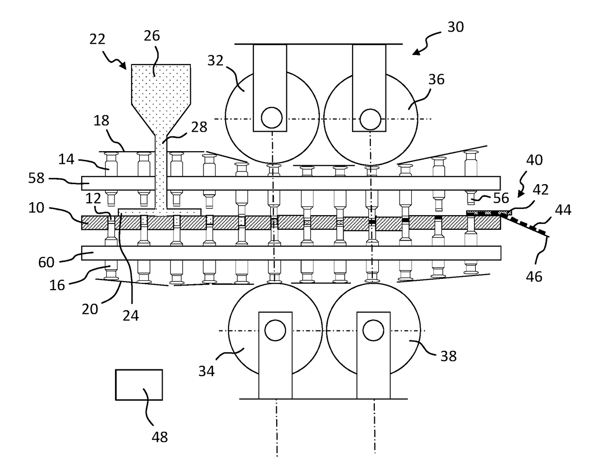
[0044]The rotary press shown in FIG. 1, in particular the rotary tablet press, comprises a rotor that is rotationally driven by a rotary drive (not shown) with a die plate 10 which has a plurality of cavities 12. The cavities 12 can for example be formed by holes in the die plate 10. Furthermore, the rotor comprises a plurality of upper punches 14 and lower punches 16 that rotate synchronously with the die plate 10. In each case, a pair consisting of an upper punch 14 and lower punch 16 is assigned to a cavity 12. The axial movement of the upper punch 14 and lower punch 16 during the rotation of the rotor is controlled by upper control cam elements 18 and lower control cam elements 20. The rotary press moreover comprises a filling apparatus 22 which has a filling chamber 24. The filling apparatus 22 further comprises a funnel-shaped filling material reservoir 26 which is connected by a feed section 28 to the filling chamber 24. In this manner, the powdered filling material in the pr...


PUM


Abstract

A punch for a rotary press comprises a shaft with a punch tip at a first end of the shaft and a punch head at the second end of the shaft. The punch head further comprises a mirror surface and a cylindrical surface, as well as intermediate region between the mirror surface and cylindrical surface. The mirror surface defining a central recess surrounded by an annular mirror surface section.

Description

CROSS REFERENCE TO RELATED INVENTION[0001]This application is based upon and claims priority to, under relevant sections of 35 U.S.C. §119, German Patent Application No. 10 2016 113 724.3, filed Jul. 26, 2016, the entire contents of which are hereby incorporated by reference.BACKGROUND[0002]The invention relates to a punch for a rotary press comprising a shaft with a punch tip at one end of the shaft and a punch head at the other end of the shaft, wherein the punch head has a mirror surface and a cylindrical surface, as well as an intermediate region between the mirror surface and cylindrical surface.[0003]Rotary presses have a plurality of upper and lower punches which can be assigned in pairs to a cavity of a die plate of the rotor of the rotary press. While the rotor is rotating, the cavities are filled with the filling material to be pressed. In a pressing apparatus, the upper and lower punches are pressed against each other in the cavities to press the filling material into pel...

Claims


Application Information

Patent Timeline
Patent Type & Authority Applications(United States)
IPC IPC(8): B30B15/06B30B15/30B30B11/04
CPCB30B15/065B30B15/302B30B11/04B30B11/08B30B15/02B30B15/0076
Inventor HEINRICH, THOMASLUEDEMANN, STEFAN
Owner FETTE ENG
Why Eureka
Try Eureka